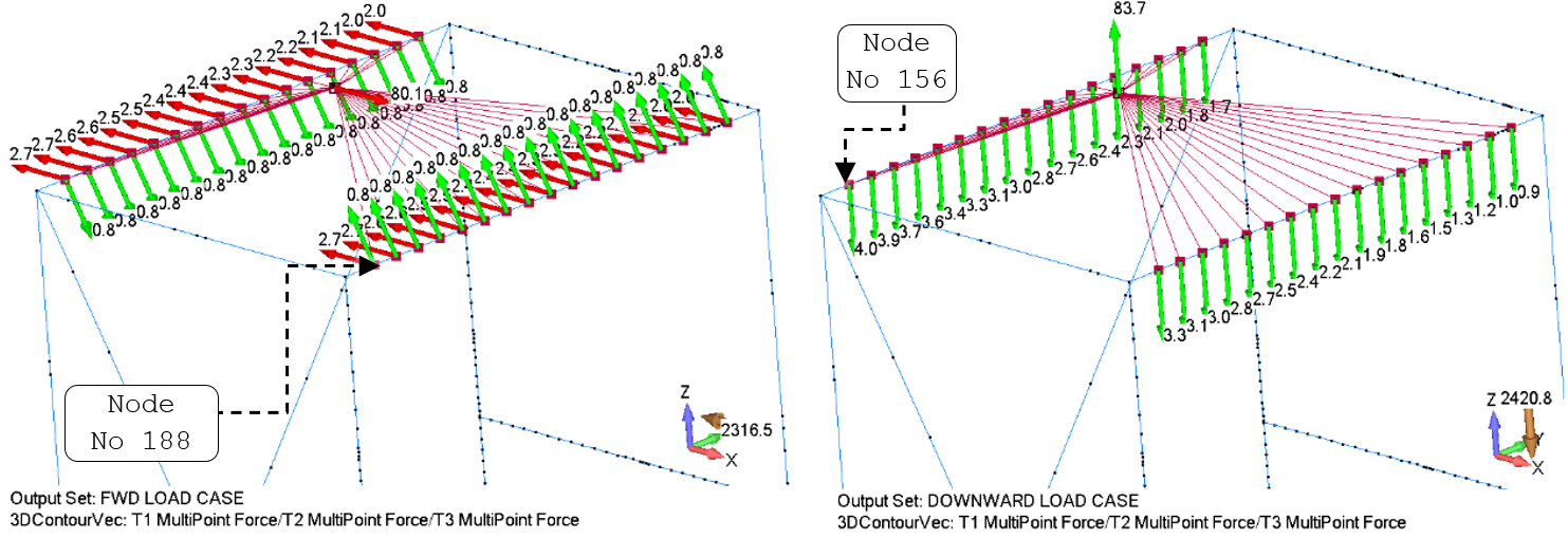
The inboard base reactions enter the aircraft through the newly installed seat-track support path.
INTRODUCTION
AircraftDHC-8-100Interior structural modification
ObjectiveStatic strength substantiationRack, attachments and supporting structure
Installation envelopeX545.00 – X580.50Mid/aft cabin floor region
Assessment routeFEA + hand substantiationLoads, joints, stresses, buckling and margins
Static-strength substantiation of an air-conditioning equipment rack installed in the DHC-8-100 cabin structure. The work combines load-envelope definition, FEMAP / SIMCENTER NASTRAN modeling, classical stress and stability checks, fastener/joint substantiation, and Python post-processing to demonstrate positive margins through the rack-to-airframe load path.
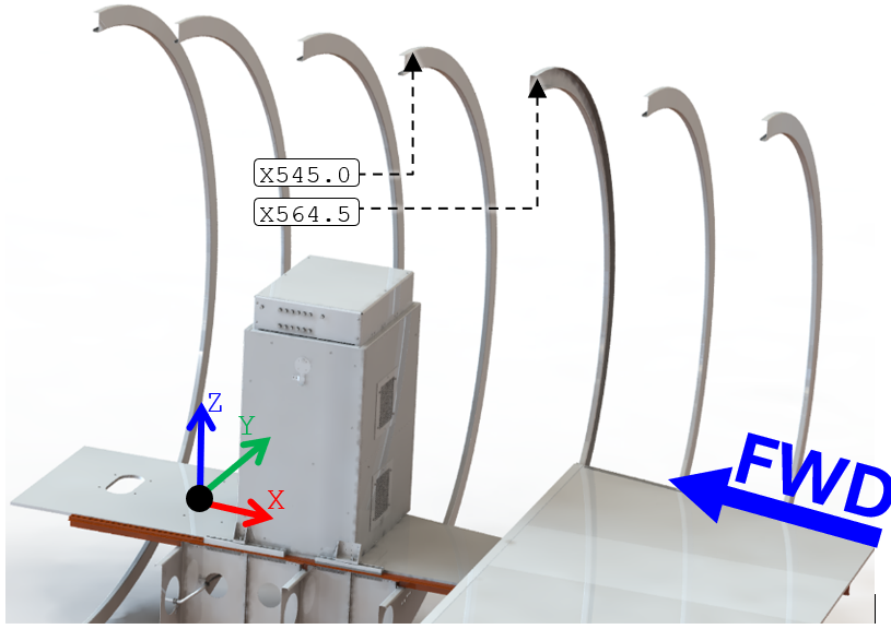
Core skillLoad-path engineeringRack → fittings → floor / track / intercostal → airframe
FEAFEMAP + NASTRANBeam, plate, CBUSH, RBE2 and RBE3 idealization
Hand substantiationStress + stability + jointsWelds, buckling, crippling, fasteners and margins
AutomationPython post-processingElement-force extraction, screening and governing-result reporting
DESIGN ASSESSMENT
The outboard base is supported by the original floor panel reinforced locally by the added intercostal.
The tube framework provides the principal load-carrying skeleton; aft and outboard skins participate structurally.
These panels provide access and maintenance functionality and are not credited as primary structural members.
The rack and its supporting structure were modeled separately because they answer different structural questions. Rack reactions are extracted and transferred into the local seat-track / floor / intercostal model, preserving the physical load path while keeping both FEMs efficient and auditable.
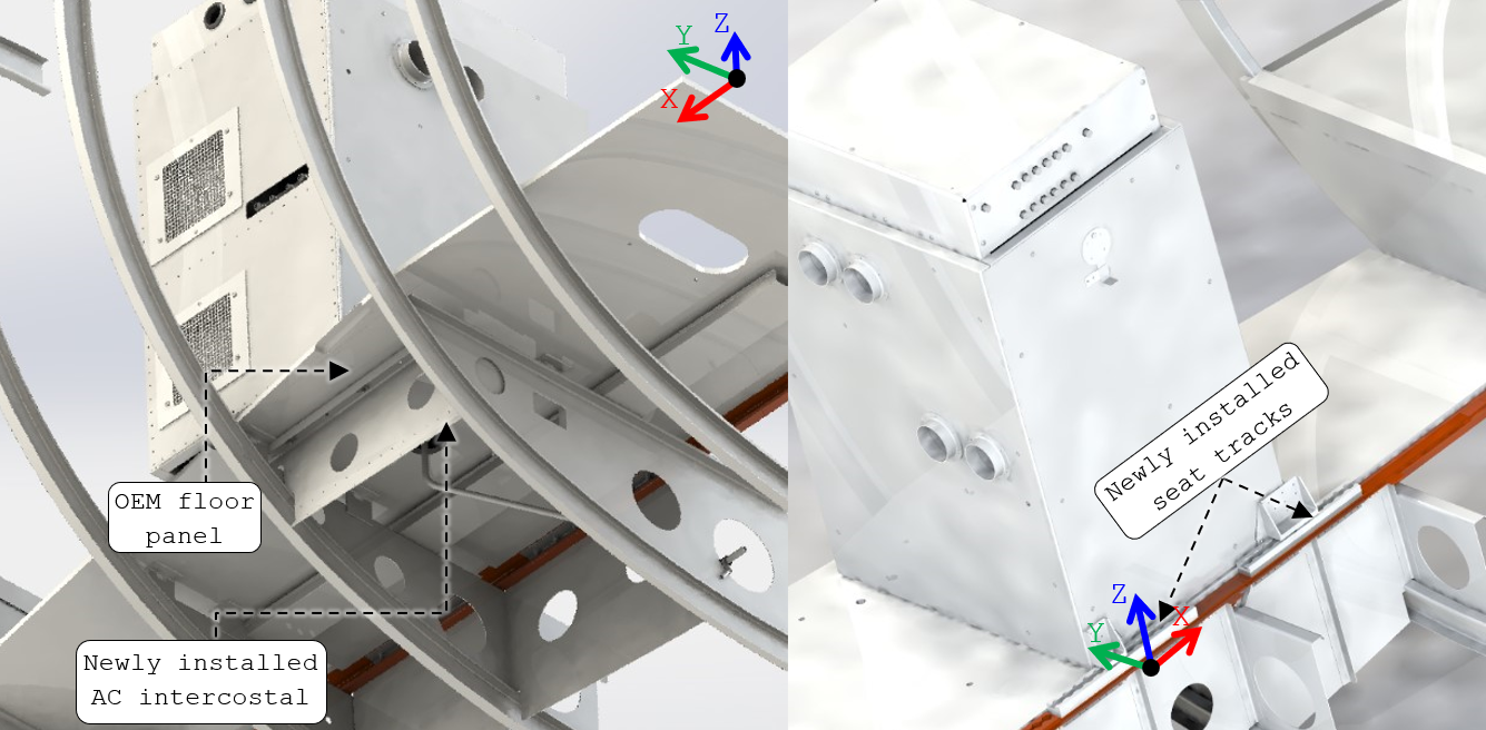
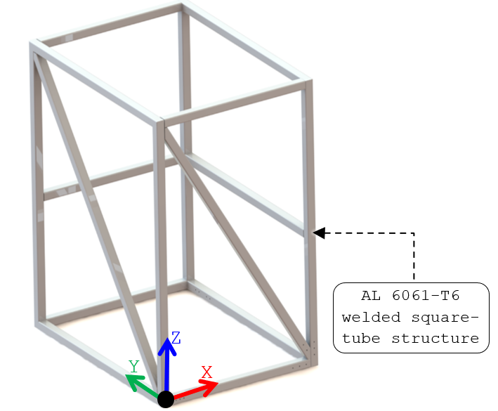
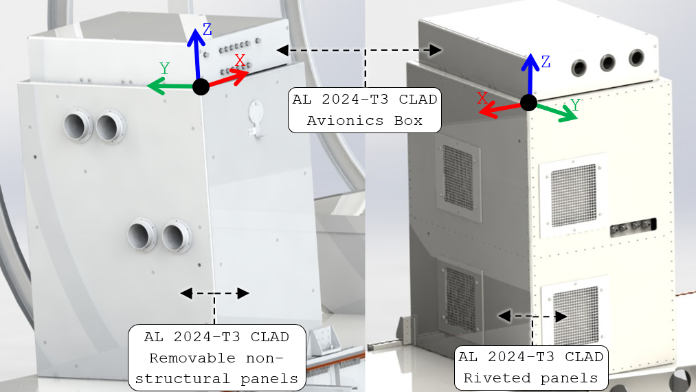
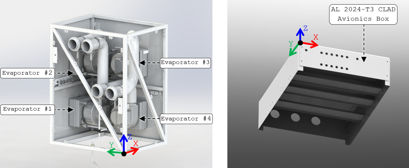
Installation Components
Only the primary load-carrying rack and newly added support components are retained here; removable access panels are not credited as primary structure.
The main structural components of the air conditioning rack.
| Component Name | Thickness [in] |
Material |
|---|---|---|
| AFT and Outboard Skin | 0.071 | AL 2024-T3 CLAD Sheet |
| AFT and FWD Gussets | 0.125 | |
| Two Base Support Clips | 0.125 | |
| Gusset Angle | 0.063 | AL 6061-T6 Extrusion |
| Attachment Angle | 0.125 | |
| Two Rack Mount Fittings | Variable | AL 6061-T6511 Extrusion |
The supporting structural components underneath the air conditioning rack
| Component Name | Thickness [in] |
Material |
|---|---|---|
| FWD and AFT Seat Tracks | 0.53 | AL 7075-T6 Extrusion |
| FWD and AFT Seat Track Support Blocks | 0.38 | AL 2024-T351 Plate |
| AC Intercostal | 0.0625 | AL 2024-T3 CLAD Sheet |
| Intercostal Attachment Brace | ||
| Large Intercostal Clip | ||
| Small Intercostal Clip | ||
| FWD Attachment Doubler |
Mass & CoG Model
Retain stiffness; idealize payload.
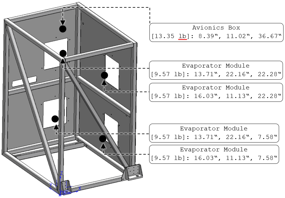
Load-bearing geometry remains explicit in the FEM. Equipment and other omitted items are represented at their center of gravity or through distributed non-structural mass so inertia is preserved without adding artificial stiffness.
Hardware / wiring allowance included.
Equipment and applicable component weights include the source 1.15 scaling factor. Material-density estimates are retained for modeled structural items and non-structural components.
Weighted-Average CoG
A worked check for the X-coordinate is:
The same procedure produces and .
Mass reconciliation. The source weight basis gives 80.50 lbf for the parts represented in the rack model. Simplified FEM geometry produced 81.839 lbf; the distributed non-structural mass was therefore reduced from 19.13 to 17.791 lbf so the model preserved the intended installation weight without adding artificial stiffness.
Supporting-structure mass model. Newly added support structure is modeled explicitly. The source structural weight is 4.07 lb and an additional 0.61 lbf (15%) is distributed as non-structural mass to represent installation hardware.
Material Properties
Strength and stability checks use the applicable material allowables from [MMPDS-15] and the cited structural-method references.
Material properties used in the Air Conditioning Rack Installation and its supporting structure.
AL 6061-T6 and T6511 Extrusion t≤1” |
AL 6061-T6 and T6511 Extrusion t=1.001”-6.5” |
AL 7075-T62 CLAD sheet t=0.04” – 0.062” |
AL 7075-T6 Extrusion t=0.25” – 0.499” |
AL 2024-T351 Plate t=0.25” – 0.499” |
AL 2024-T3 CLAD Sheet t=0.063” – 0.128” |
AL 2024-T3 Sheet t=0.010” – 0.128” |
Unit | |
|---|---|---|---|---|---|---|---|---|
| Ftu | 38 | 38 | 69 | 81 | 64 | 62 | 64 | ksi |
| Fty | 35 | 35 | 61 | 73 | 48 | 45 | 47 | ksi |
| Fcy | 34 | 34 | 62 | 73 | 39 | 37 | 39 | ksi |
| Fsu | 26 | 19 | 47 | 43 | 38 | 38 | 39 | ksi |
| Fbru | 82 | 69 | 142 | 146 | 119 | 125 | 129 | ksi |
| Fbry | 60 | 50 | 109 | 113 | 86 | 84 | 88 | ksi |
| E x103 | 9.90 | 9.90 | 10.3 | 10.4 | 10.7 | 10.50 | 10.5 | ksi |
| Ec x103 | 10.10 | 10.10 | 10.5 | 10.7 | 10.9 | 10.70 | 10.7 | ksi |
| μ | 0.33 | 0.33 | 0.33 | 0.33 | 0.33 | 0.33 | 0.33 | - |
| ρ | 0.098 | 0.098 | 0.101 | 0.101 | 0.1 | 0.1 | 0.1 | lbm/in3 |
| G x103 | 3.80 | 3.8 | - | 4.0 | 4.0 | - | 4.0 | ksi |
| e | 8 or 10 | 10 | 9 | 7 | 12 | 15 | 12 or 15 | % |
Fastener / Joint Allowables
Joint allowable philosophy
Use the weakest applicable failure path for the actual fastener / sheet stack rather than the isolated fastener strength.
Sheet thickness and material alter joint strength.Countersunk geometry uses the applicable static-joint reduction.Bearing is checked at the critical sheet / hole interface.
Detailed joint allowables were established from the actual sheet stack, fastener type, countersink condition and bearing path using [MMPDS-15], Bruhn and the applicable vendor data. The compact cards below retain the hardware families used in the analysis; the governing result checks later use the joint-specific allowables.
CR3212 · ARM4
Type Countersunk blind rivetNominal size 1/8 inSingle shear 664 lbfTension 285 lbfRivet / hole Ø 0.125 / 0.1285 inApplied joints J7–J10
CR3213 · ARN4
Type Protruding blind rivetNominal size 1/8 inSingle shear 664 lbfTension 285 lbfRivet / hole Ø 0.125 / 0.1285 inApplied joints J3–J6
MS20426AD4 · BB4
Type Countersunk solid rivetMaterial AL 2117-T3Material Fsu 30 ksiSingle shear 389 lbfApplied joint J25
MS20470AD4 · BJ4
Type Protruding solid rivetMaterial AL 2117-T3Material Fsu 30 ksiSingle shear 389 lbfApplied joints J11–J24
MS24694-S49
Type #10-32 countersunk screwThread UNF-3A · MIL-S-7742Diameter 0.19 inMaterial Cadmium-plated carbon steelFtu 125 ksiFsu 75 ksiApplied joints J28–J29
AN3 / AN4 Aircraft Bolt
Thread 1/4-28 UNF-3ADiameter 0.25 inMaterial Non-corrosion-resistant steelUltimate shear 3,680 lbfUltimate tension 4,080 lbfApplied joint J30
FE200744 Stud + Lock Fitting
Thread 3/8-24 UNRFDiameter / length 0.375 / 0.9 inMaterial Zinc-plated carbon steelTrack shear 4,200 lbfTrack tension 5,700 lbfApplied joints J1–J2
LOAD CASES FORMULATION
Interior installation → evaluate both flight and emergency conditions.
The governing directional case is selected by comparing the worst flight acceleration with the equivalent limit form of the emergency-landing requirement.
REGULATORY SOURCE BASISFAR Part 25 criteria used to formulate the structural load envelope
Flight-load framework
FAR 25.321 and 25.331–25.351
- General flight loads and symmetric maneuver response
- Flight maneuver envelope and design airspeeds
- Limit maneuver factors, gust and turbulence loads
- Fuel/oil, high-lift, rolling and yaw conditions
Emergency landing
FAR 25.561
- Forward: 9 g
- Downward: 6 g
- Upward: 3 g
- Sideward: 3 g airframe / 4 g seats & attachments
- Rearward: 1.5 g
The rack center is taken at X563.58. Flight accelerations were interpolated at that station and compared direction-by-direction with the equivalent limit form of the FAR 25.561 emergency-landing requirements. The five governing FEM cases are retained below; the 1.5 ultimate factor is applied in the reported margins.
Governing limit-load cases applied to the FEM.
| Case | Direction | Flight limit [g] |
Emergency equivalent [g] |
Applied [g] |
Governing basis |
|---|---|---|---|---|---|
| 1 | Upward | 5.92 | 2.00 | 5.92 | Flight |
| 2 | Downward | -6.27 | -4.00 | -6.27 | Flight |
| 3 | Outboard | 1.82 | 2.00 | 2.00 | Emergency landing |
| 4 | Inboard | -1.82 | -2.00 | -2.00 | Emergency landing |
| 5 | Forward | -0.61 | -6.00 | -6.00 | Emergency landing |
| - | Aft | 0.16 | 1.00 | Not separately required | Covered conservatively by Forward case |
I compared flight and emergency conditions direction by direction and retained only the larger absolute limit acceleration. This prevented duplicate cases while preserving the governing regulatory demand. The FEM therefore contained five clearly traceable load cases rather than separate, overlapping flight and emergency models.
FINITE ELEMENT MODEL (FEM)
Air Conditioning Rack Model
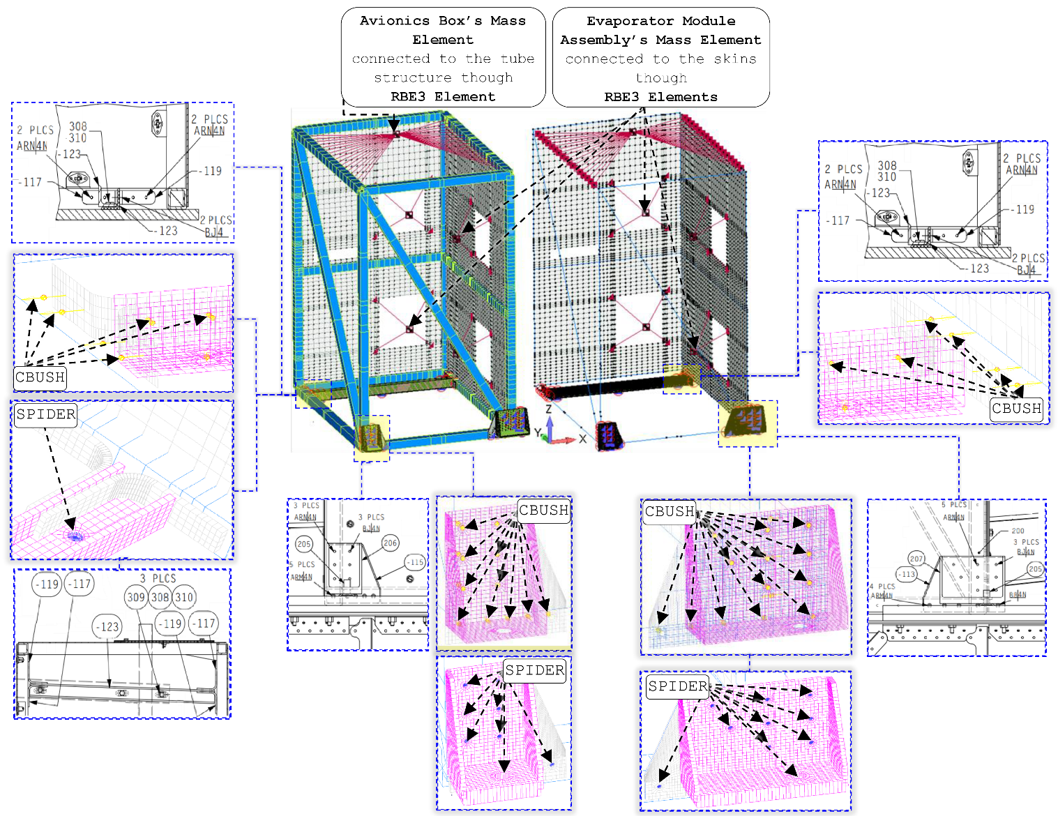
Non-structural detail is omitted geometrically, not inertially.
Exterior removable panels and small hardware are excluded from the mesh; their equivalent weight is distributed over the tube structure as NSM.
Beam · tube structure
The welded square-tube frame is modeled with beam elements so section area, inertia, axial force, shear and bending are recovered efficiently along the primary load path.
Plate · skins, gussets & brackets
Six material/thickness plate properties represent the aft/outboard skins, gussets, base clips, gusset/attachment angles and rack-mount fittings. The thin-walled parts are governed by membrane and bending response rather than through-thickness stress.
CBUSH · mounting fasteners
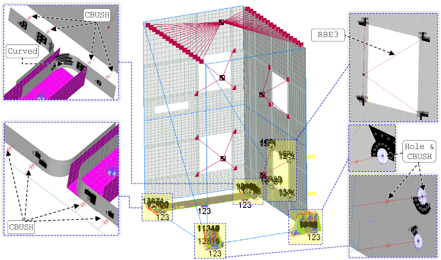
Rack-mount, base-clip and attachment-angle fasteners use 1×10⁹ lbf/in translational stiffness with free rotations. This transfers shear/tension without imposing artificial rotational fixity.
RBE2 · fastener-hole spiders
Modeled attachment holes use RBE2 spiders to distribute connector reactions over the hole perimeter. Non-governing holes are suppressed to avoid artificial local stress peaks that do not control the primary load path.
RBE3 · equipment masses
The four evaporator modules and avionics box are introduced as point masses through RBE3 elements, transferring inertia to the structure without adding rigid-body stiffness.
Glued vs. non-penetrating interfaces
Opposing attachment-angle faces are glued where full transfer is intended; rack-fitting/gusset and skin interfaces use non-penetrating contact so compression is transferred without unrealistically bonding every interface.
Loads & Constraints
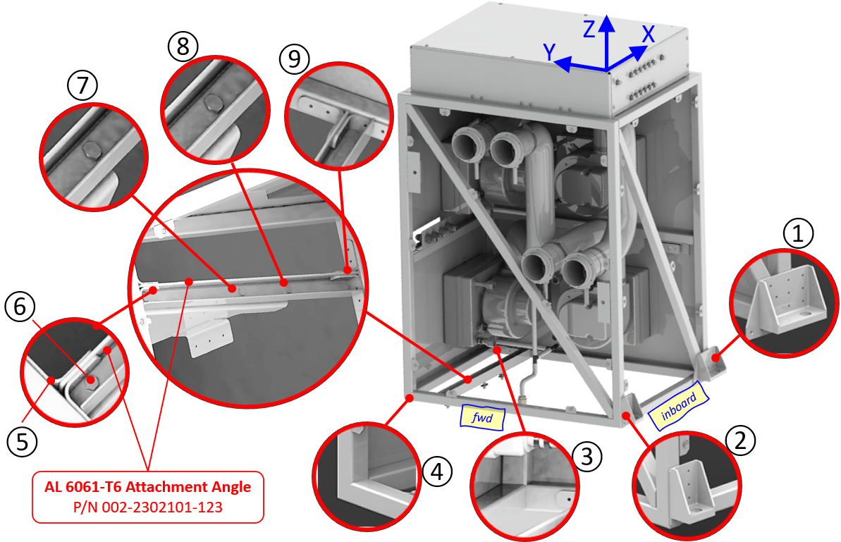
Body accelerations are applied to the rack for the five governing cases. Restraints are changed by load direction to represent the actual attachment capability rather than imposing one artificially fixed boundary condition for every case.
The restrained degrees of freedom (DoFs) at each Attachment Points for each load case.
| FWD | Inboard | Outboard | Upward | Downward | |
|---|---|---|---|---|---|
| ① | TxTyTz | TxTyTz | TxTyTz | TxTyTz | TxTyTz |
| ② | TxTyTz | TxTyTz | TxTyTz | TxTyTz | TxTyTz |
| ③ | Free | Free | Tz | Free | Tz |
| ④ | Tz | Free | Tz | Free | Tz |
| ⑥ | TxTyTz | TxTyTz | TxTyTz | TxTyTz | TxTyTz |
| ⑦ | TxTyTz | TxTyTz | TxTyTz | TxTyTz | TxTyTz |
| ⑧ | TxTyTz | TxTyTz | TxTyTz | TxTyTz | TxTyTz |
Supporting Structure Model
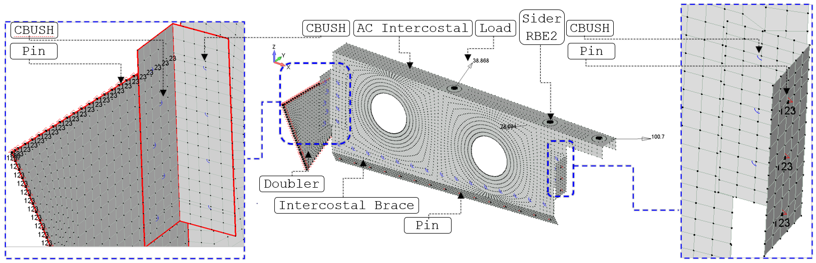
Beam · seat tracks / blocks / T-section
These members are represented by beam properties because axial and bending response is governed primarily by section properties; solid modeling would add cost without improving the global load-path solution.
Grounded CBUSH · existing structure
Grounded connectors at the pre-existing T-section track represent the restraint delivered by adjacent webs, stiffeners and frames while avoiding a need to model the entire surrounding fuselage.
CBUSH · seat-track screws
MS24694-S49 and NAS8603-12 screws use high translational stiffness with free rotations. The connector captures global shear/tension transfer without introducing detailed bolt contact and thread geometry.
RBE2 · track end coupling
Seat-track end points rigidly transfer the selected Ty and Rx motions into the T-section support path, reproducing the constrained interface behavior without over-modeling the surrounding airframe.
Plate · intercostal / doubler / clips / brace
Thin structural sheet components are modeled with plate elements to recover membrane, bending and shear response directly. Through-thickness solid stress is non-governing for the global substantiation.
Directional CBUSH stiffness
MS20470AD4 rivets use 1×10⁹ lbf/in in shear and 1×10⁵ lbf/in in tension with free rotations, reflecting a shear-dominant riveted joint without artificially rigid tensile restraint.
Physical interfaces retained
Non-penetrating contact allows compression and relative interface motion where appropriate; glued contact is used only where the assembly is intended to transfer load continuously.
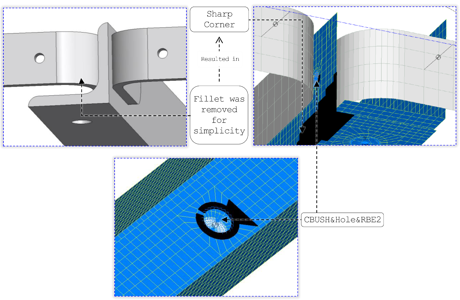
RBE2 spider · outboard attachment
Concentrated rack reactions are distributed around the fastener-hole perimeter to suppress node singularities and provide a stable, physically meaningful load introduction into the sheet structure.
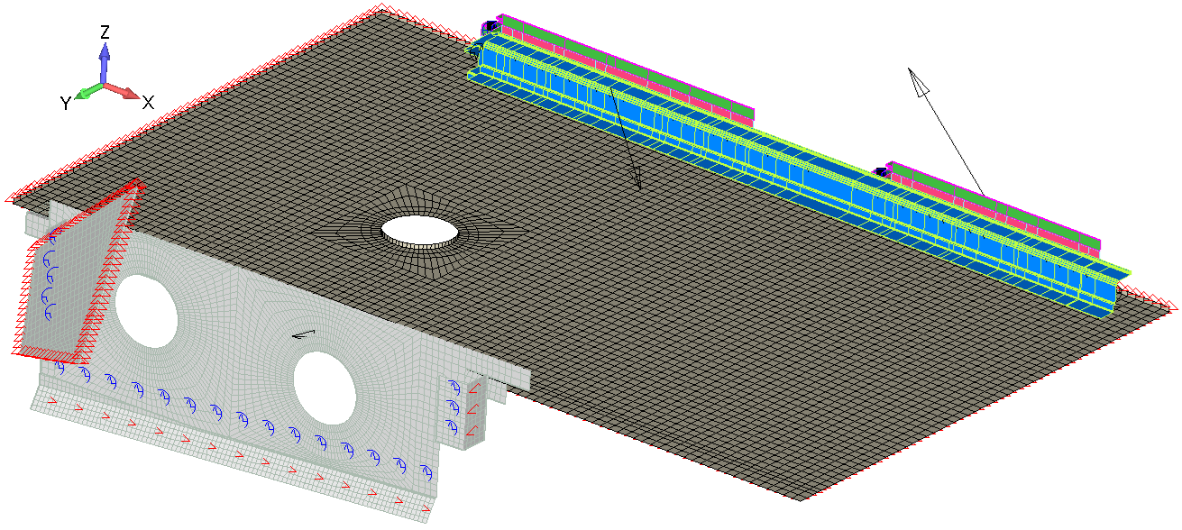
Equivalent floor-panel idealization. The sandwich floor is represented by an equivalent plate that preserves the required global flexural rigidity and distributed-load transfer. This is appropriate for rack-support substantiation; local core crushing and face-sheet delamination are outside the scope of the global plate idealization.
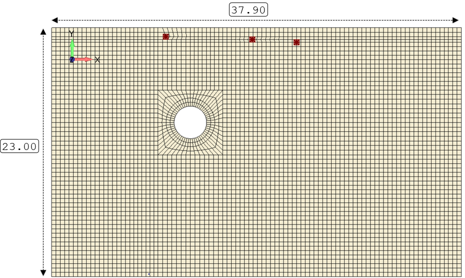
The sandwich floor is represented by a homogeneous AL 2024-T3 CLAD plate for the global support-model analysis. The source model preserves the required global bending/load-transfer response while excluding local sandwich failure modes such as core crushing and face-sheet delamination.
The equivalent plate is checked against the cargo-floor downward limit demand:
For a simply supported rectangular plate under uniform pressure, the maximum bending stress is:
β - plate coefficientb - smaller panel dimensiont - equivalent plate thicknessq - uniform pressure
Using , the minimum required thickness becomes:
For a 37.90 in × 23.00 in panel, . Linear interpolation of the source plate coefficient gives:
With , the source check gives:
✓The equivalent-plate idealization is therefore supported by a 0.189 in minimum-thickness check for the stated cargo-floor limit demand.
Method basis: [Formulas for Stress & Strain-Raymond Roark-Table 11.4] and [MMPDS-15-Table 3.2.4.0(c1)].
Transferred Loads & Support Constraints
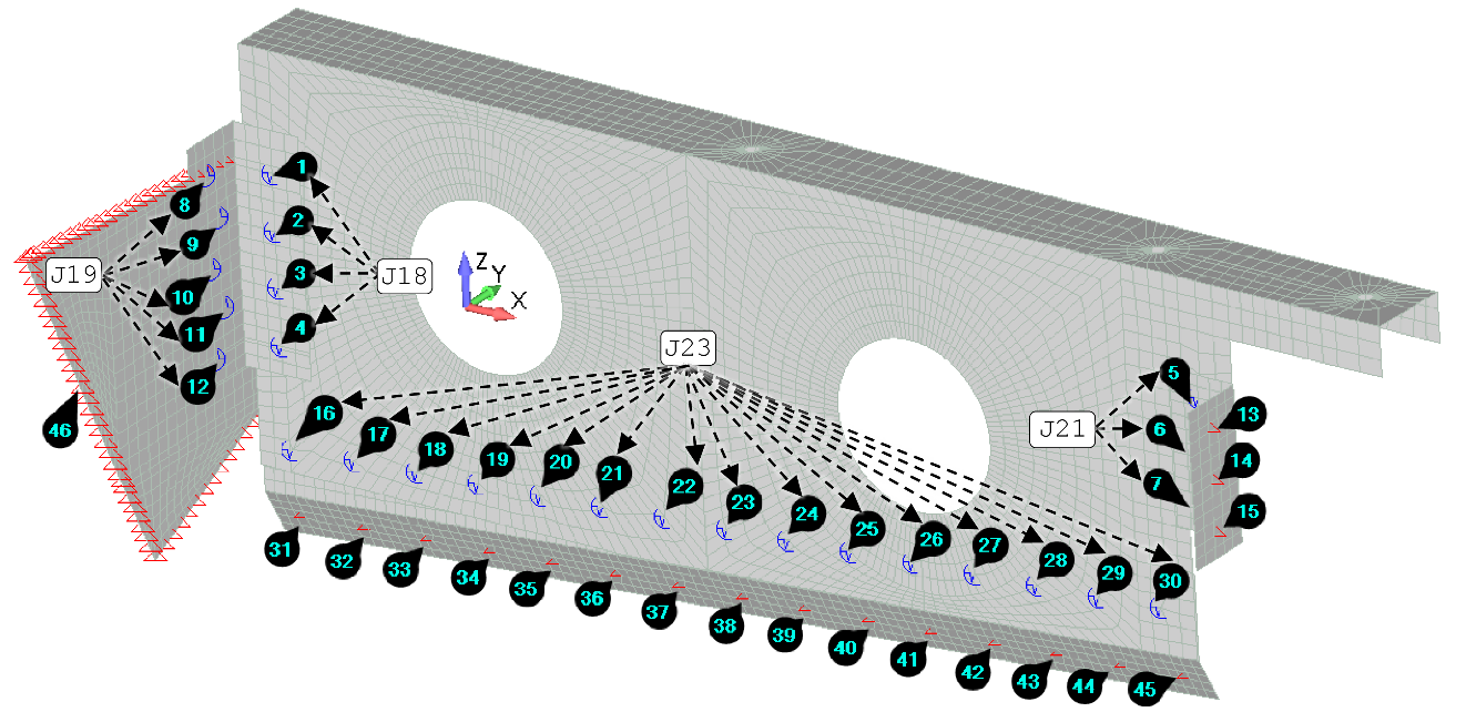
Rack-model reactions are applied at the corresponding support-model attachment locations. Floor edges, doubler edges, the AFT clip and intercostal brace are restrained as defined in the source model, preserving load-path continuity from the equipment rack into the local aircraft structure.
All Nodes at the Floor Edges.
All Nodes at the Doubler Edges.
Three Nodes at the AFT Side of the AFT Clip.
Fifteen Nodes at the Bottom Side of the Intercostal Brace.
Analysis
Linear static response is appropriate for the defined ultimate/limit load cases and the global strength checks performed here.
Member forces, plate stresses, connector reactions and constraint forces are recovered for downstream hand checks and margins.
WTMASS enabled
Mass is entered in lbm, density in lbm/in³ and acceleration in in/s². WTMASS provides consistent mass-to-force conversion so solver forces are recovered in lbf and stresses in psi.
FEA RESULTS
Governing reported MS+0.08AL 6061-T6 / T6511 principal-stress check
Primary frameTube + welds passCombined stress, buckling and crippling assessed
Joint substantiationPositive marginsMain attachments, skins, rack fittings and intercostal joints
Post-processingAutomated screeningPython evaluates all valid plate elements and load cases
Governing strength checks retained in this portfolio summary. All margins shown are the reported source-calculation values.
| Check | Governing reported result | Minimum MS | Status |
|---|---|---|---|
| Welded tube structure | Combined tube / weld stress | +0.54 | PASS |
| Tube column buckling | 40 in critical member; source buckling check | +1.08 | PASS |
| AL 2024-T3 CLAD sheet | Principal-stress assessment | +0.13 | PASS |
| AL 6061-T6 / T6511 | Principal-stress assessment | +0.08 | PASS |
| Attachment-angle crippling | Needham / Gerard method | +0.40 | PASS |
| Intercostal-flange crippling | Needham / Gerard method | +1.39 | PASS |
| AN4 / insert attachment | Main outboard attachment shear | +0.82 | PASS |
| AFT skin CR3212 rivets | Tension governs source check | +0.76 | PASS |
| Rack-mount CR3213 rivets (J3) | Tension governs source check | +0.37 | PASS |
| AFT-gusset CR3212 rivets (J8) | Fail-safe redistributed shear | +0.41 | PASS |
Tube Structure & Welds
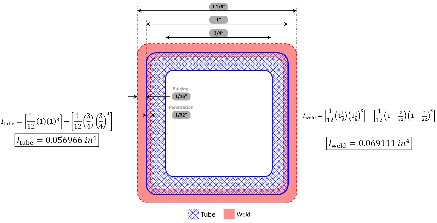
Weld stress treatment. Tube member forces are recovered from the beam model, then converted to weld-section stresses using the actual weld/tube section-property ratios. This avoids modeling weld beads with solid elements while retaining the conservative change in area and bending section modulus.
The beam model recovers member axial force and bending moments. Weld stresses are then mapped from the tube section using the actual section-property ratios:
The Maximum Axial Force and Bending Moments values for each load case. The highlighted values are the global maximum values. The results are due to applied limit loads.
| FWD | INBOARD | OUTBOARD | UPWARD | DOWNWARD | |
|---|---|---|---|---|---|
| M1 [in-lbf] | 599.91 | 78.78 | -54.30 | 168.86 | 75.59 |
| M2 [in-lbf] | 357.98 | -232.82 | -52.71 | -559.06 | 136.81 |
| Axial [lbf] | 420.84 | -87.34 | 69.40 | 146.70 | -144.33 |
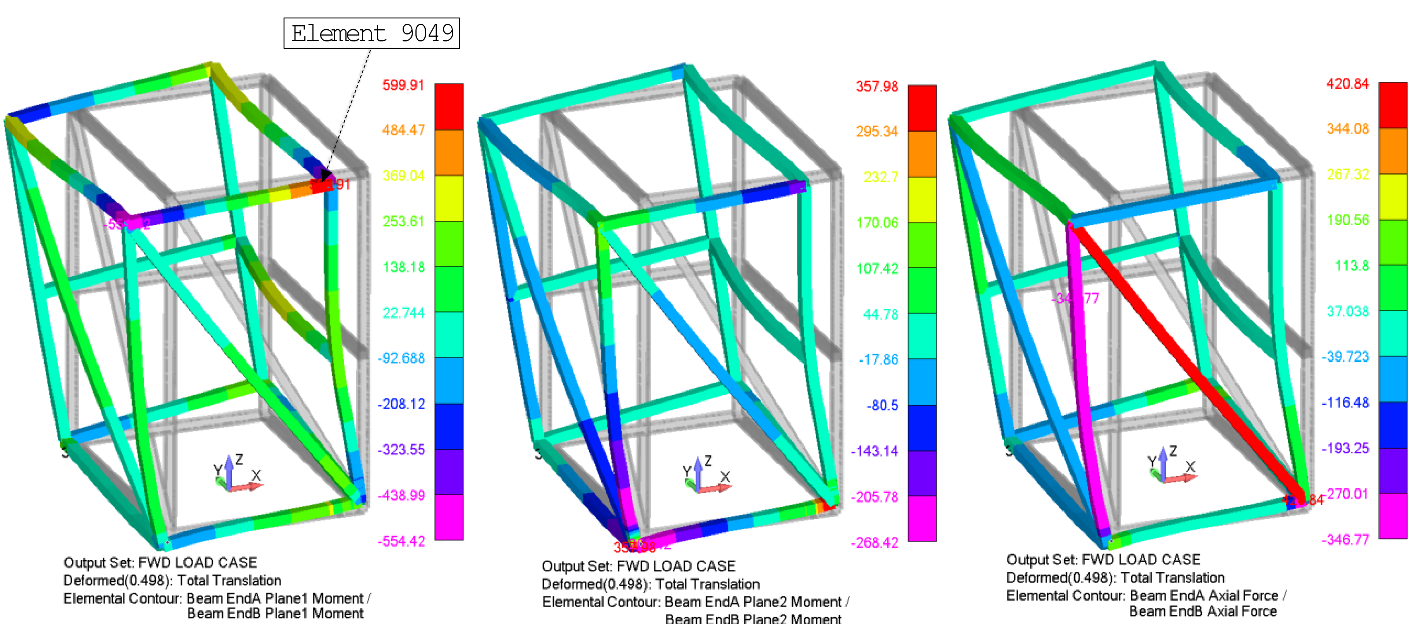
The source element-by-element combination identifies the forward case as governing. The minimum reported static-strength margin for the tube / weld assessment is retained below.
→ PASS
Stability checks. The 40 in critical member was checked for Euler-type column buckling using pinned-pinned and fixed-fixed bounds; the source averaged critical stress is 20.28 ksi and the reported buckling margin is +1.08. A Needham / Gerard crippling check gives a 75.07 ksi section crippling allowable, so the tube section also passes the source crippling assessment.
→ PASS
| Angle # | h | th | b | tb | An | Ce | Fccn | AnFccn |
|---|---|---|---|---|---|---|---|---|
| 1 | 0.500 | 0.125 | 0.500 | 0.125 | 0.125 | 0.366 | 75.075 | 9.384 |
| 2 | 0.500 | 0.125 | 0.500 | 0.125 | 0.125 | 0.366 | 75.075 | 9.384 |
| 3 | 0.500 | 0.125 | 0.500 | 0.125 | 0.125 | 0.366 | 75.075 | 9.384 |
| 4 | 0.500 | 0.125 | 0.500 | 0.125 | 0.125 | 0.366 | 75.075 | 9.384 |
| Σ | 0.500 | 37.537 | ||||||
FCrippling [ksi] |
75.07 |
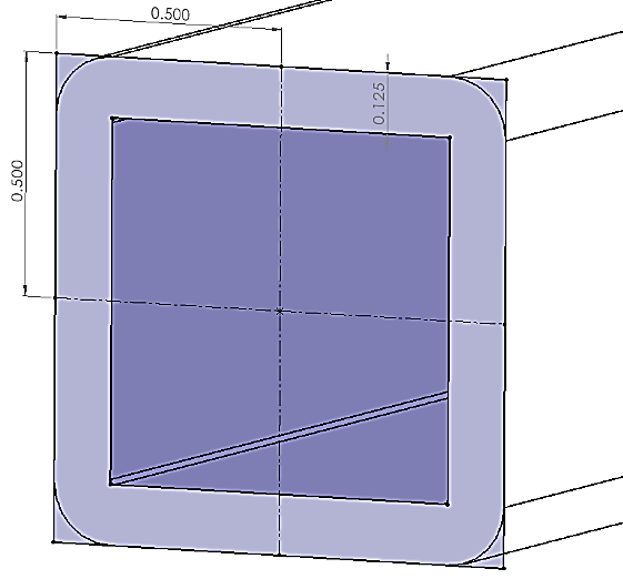
Plate & Sheet-Metal Checks
Purpose: prevent mesh singularities, geometric discontinuities, and other non-representative local peaks from governing the global strength assessment without engineering review.
- Screen the global maximum and minimum principal stresses.
- Define material-specific tensile and compressive threshold values.
- Flag elements above the tensile threshold or below the compressive threshold.
- Review each flagged location in the FEM and identify non-representative numerical/localized peaks.
- Exclude only the confirmed non-representative elements from the failure assessment.
- Recalculate the governing principal stresses from the remaining elements and compare them with Ftu and Fcy.
- Retain any remaining critical elements within the thresholds as part of the conservative assessment.
This preserves conservative structural coverage while reducing the influence of numerical artifacts on the reported governing stress.
AL 2024-T3 CLAD Sheet
After engineering review of localized numerical peaks, the source assessment retains 28.08 ksi maximum tensile and 21.81 ksi maximum compressive principal stress for the failure check. Against 62 ksi tensile and 37 ksi compressive allowables, the reported governing margin is +0.13.
→ PASS
AL 6061-T6 / T6511 Extrusion
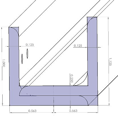
The reviewed source result retains 23.00 ksi maximum tensile and 20.95 ksi maximum compressive principal stress. Against 38 ksi and 34 ksi allowables, the reported governing margin is +0.08. The attachment-angle crippling calculation gives a 44.06 ksi allowable and +0.40 margin.
→ PASS
| Angle # | h | th | b | tb | An | Ce | Fccn | AnFccn |
|---|---|---|---|---|---|---|---|---|
| 1 | 1.000 | 0.125 | 0.563 | 0.250 | 0.391 | 0.342 | 50.184 | 19.610 |
| 2 | 1.125 | 0.125 | 0.563 | 0.250 | 0.422 | 0.342 | 47.371 | 19.990 |
| Σ | 1.040 | 45.833 | ||||||
FCrippling [ksi] |
44.06 |
→PASS
Supporting Structure Sheets
Maximum and Minimum Principal Stresses for the Structural Sheet Metals. The highlighted cells represent the global maximum tensile and compressive principal stresses. The results are due to applied limit loads.
AL 2024-T3 CLAD Sheet [t=0.063” – 0.128”] |
FWD | UP | DOWN | IN | OUT | MAX Tension [ksi] |
MAX Compression [ksi] |
||||||
|---|---|---|---|---|---|---|---|---|---|---|---|---|---|
| F1 [ksi] |
F2 [ksi] |
F1 [ksi] |
F2 [ksi] |
F1 [ksi] |
F2 [ksi] |
F1 [ksi] |
F2 [ksi] |
F1 [ksi] |
F2 [ksi] |
||||
| Top | Tension | 11.82 | 3.61 | 12.13 | 3.72 | 0.27 | 0.04 | 4.91 | 1.51 | 0.73 | 0.21 | 12.15 | 8.29 |
| Compression | 1.11 | 3.45 | 1.86 | 4.66 | 0.06 | 0.33 | 0.74 | 1.82 | 0.08 | 0.70 | |||
| Bot | Tension | 11.85 | 3.94 | 12.15 | 4.06 | 0.29 | 0.11 | 4.93 | 1.65 | 0.73 | 0.23 | ||
| Compression | 5.42 | 6.93 | 6.36 | 8.29 | 0.16 | 0.42 | 2.55 | 3.30 | 0.52 | 1.04 | |||
AL 2024-T3 CLAD Sheet [t=0.129"-0.249"] |
FWD | UP | DOWN | IN | OUT | MAX Tension [ksi] |
MAX Compression [ksi] |
||||||
| F1 [ksi] |
F2 [ksi] |
F1 [ksi] |
F2 [ksi] |
F1 [ksi] |
F2 [ksi] |
F1 [ksi] |
F2 [ksi] |
F1 [ksi] |
F2 [ksi] |
||||
| Top | Tension | 10.79 | 8.02 | 10.75 | 7.96 | 0.19 | 0.12 | 4.34 | 3.21 | 0.77 | 0.55 | 10.79 | 8.63 |
| Compression | 3.76 | 4.74 | 4.43 | 5.21 | 0.20 | 0.26 | 1.80 | 2.12 | 0.21 | 0.35 | |||
| Bot | Tension | 3.48 | 2.66 | 3.86 | 3.05 | 0.21 | 0.11 | 1.57 | 1.24 | 0.33 | 0.17 | ||
| Compression | 5.96 | 7.91 | 6.78 | 8.63 | 0.13 | 0.27 | 2.73 | 3.44 | 0.50 | 0.84 | |||
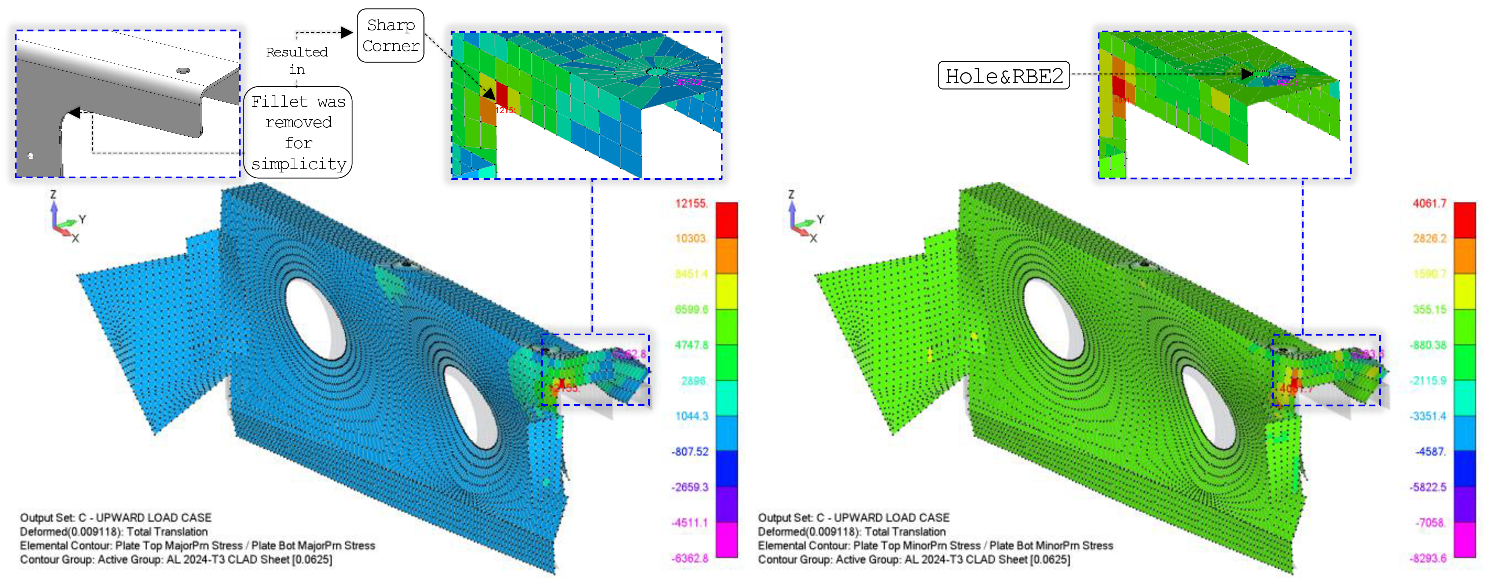
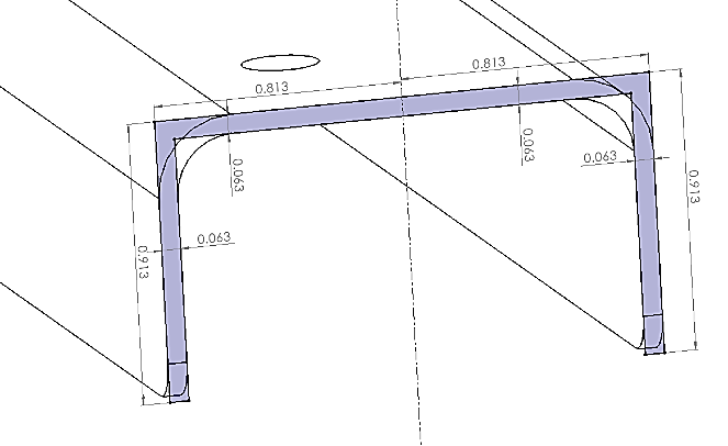
The support-model plates are reviewed across all five load cases. Localized high gradients are retained conservatively in the source assessment where appropriate; the intercostal flange is additionally checked for crippling.
| Angle # | h | th | b | tb | An | Ce | Fccn | AnFccn |
|---|---|---|---|---|---|---|---|---|
| 1 | 0.913 | 0.063 | 0.813 | 0.063 | 0.108 | 0.342 | 29.759 | 3.210 |
| 2 | 0.913 | 0.063 | 0.813 | 0.063 | 0.108 | 0.342 | 29.759 | 3.210 |
| Σ | 0.216 | 6.421 | ||||||
FCrippling [ksi] |
29.76 |
→ PASS
Fasteners & Attachments
Main Attachment Points
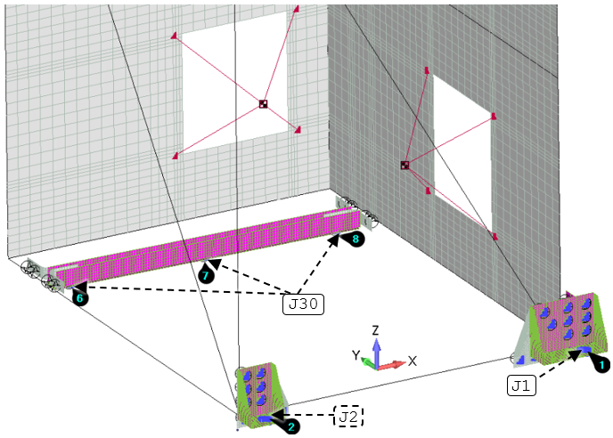
Inboard: two ANCRA single-stud fittings carry maximum source limit loads of 309.37 lbf shear and 430.37 lbf tension in the forward case. Outboard: the AN4-11A / insert attachment reaches 626.66 lbf shear and 336.75 lbf tension in the upward case.
→ PASS
→ PASS
→ PASS
→ PASS
AFT Skin Rivets & Python Post-Processing
The plate-force post-processing was automated to reduce repetitive manual work and improve traceability. The script reads FEMAP-exported element and nodal data, rejects triangular elements, calculates element dimensions, converts membrane resultants to elemental forces, screens all load cases, and writes governing results to a summary workbook.
- Read the FEMAP Excel export and nodal coordinates.
- Extract nodal-coordinate values (X-Def, Y-Def, Z-Def).
- Filter valid quadrilateral plate elements.
- Calculate element dimensions and local force directions.
- Recover nx, ny, nxy, qx, and qy for every element and load case.
- Calculate elemental shear and tensile demand.
A conservative in-plane resultant is calculated as:
- Generate contour maps and a governing-result summary.
- 2D plot of elements and nodes.
- Heat maps for maximum shear load and maximum tensile load for every load case.
- Extract maximum membrane forces, shear, and tensile loads from each load case and save them to a new summary table.
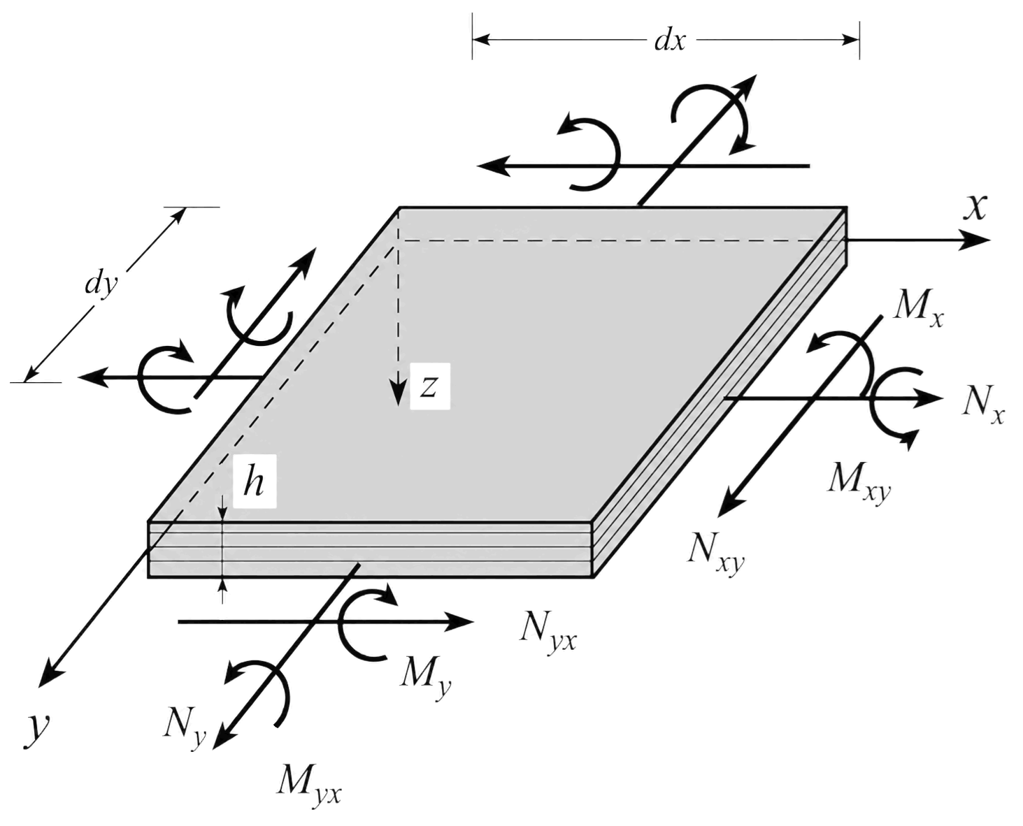
Why I automated this stepThe governing plate element was not necessarily the element with the largest individual nx, ny, or nxy component. Automation allowed every valid plate element and load case to be evaluated using one documented equation set, eliminating inconsistent spreadsheet manipulation and preserving a repeatable audit trail.
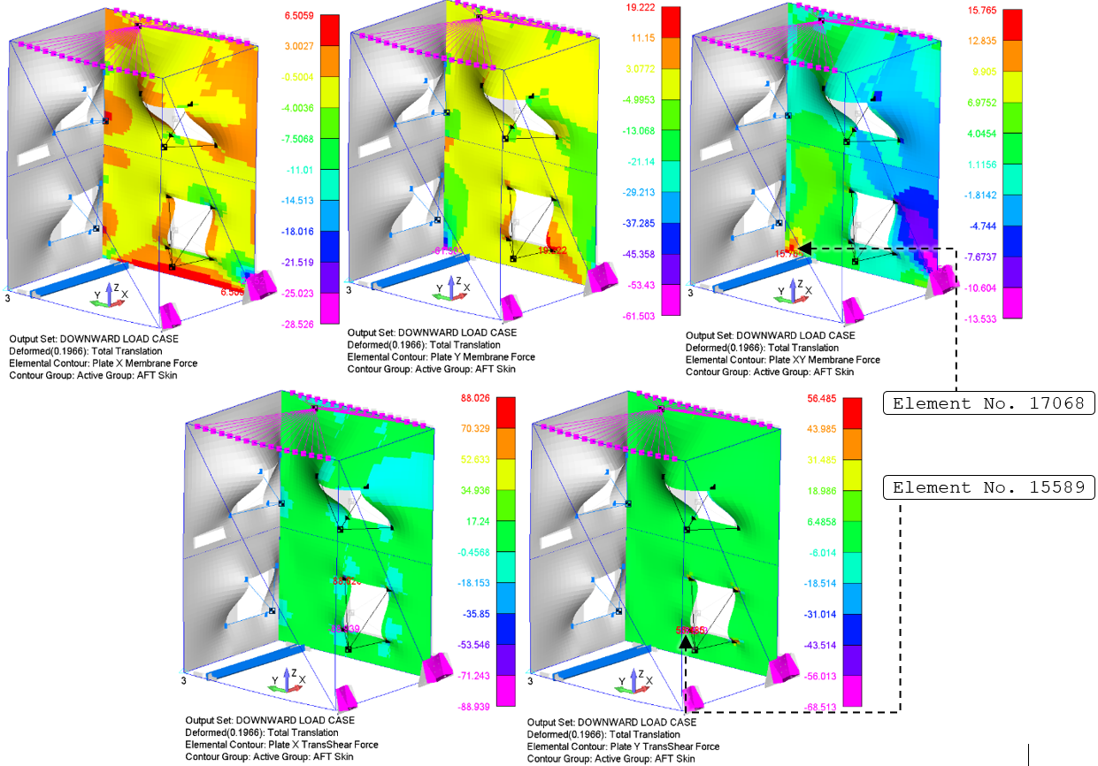
The Maximum Elements’ Plate, Shear, and Tensile Forces and the resulted maximum Shear and Tensile loads for all load cases. The results are due to applied limit loads.
| Load Case | Nx,max [lbf] |
Ny,max [lbf] |
Nxy-x,max [lbf] |
Nxy-y,max [lbf] |
Qx,max [lbf] |
Qy,max [lbf] |
fs,max [lbf] |
ft,max [lbf] |
|---|---|---|---|---|---|---|---|---|
| FWD | 21.45 | 27.02 | 9.34 | 12.52 | 4.61 | 5.08 | 38.18 | 6.06 |
| INBD | 6.06 | 14.06 | 3.28 | 5.74 | 10.81 | 9.61 | 21.89 | 11.56 |
| OUTBD | 11.10 | 9.81 | 5.09 | 7.37 | 4.57 | 9.87 | 20.59 | 8.93 |
| UPWD | 11.16 | 33.52 | 9.14 | 14.96 | 26.05 | 12.83 | 36.54 | 22.91 |
| DOWNWD | 3.11 | 11.38 | 6.62 | 11.74 | 26.94 | 36.99 | 40.17 | 37.66 |
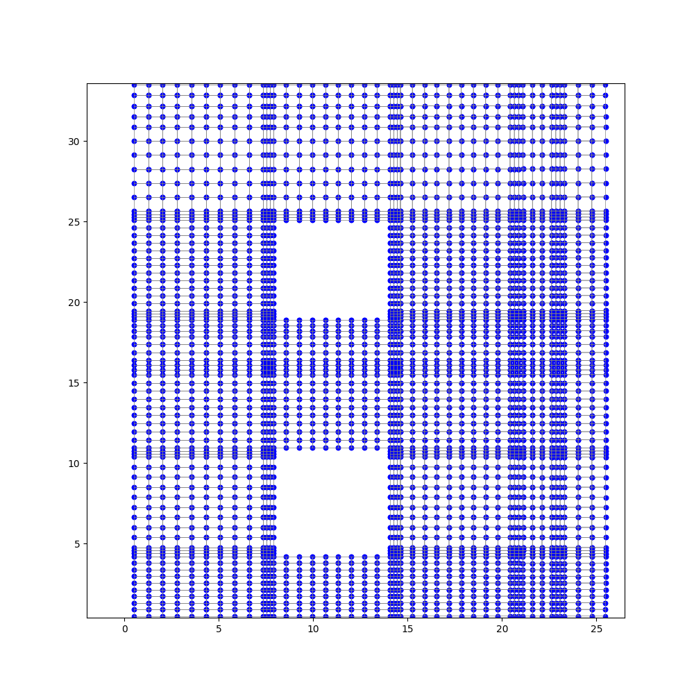
The automated screening identifies the source governing AFT-skin rivet demands as 38.86 lbf shear and 37.65 lbf tension under the downward case. The resulting reported margins are:
→ PASS
→ PASS
The avionics box is attached by 17 CR3213 rivets per side. FEM multipoint forces are low (4.03 lbf maximum shear and 2.72 lbf maximum tension). A conservative 3D rigid-body check assuming only two rivets per side increases the evaluated maxima to 27.96 lbf shear and 22.04 lbf tension; the source concludes the joint passes by observation.
Rack-Mount Fittings & Fail-Safe Check
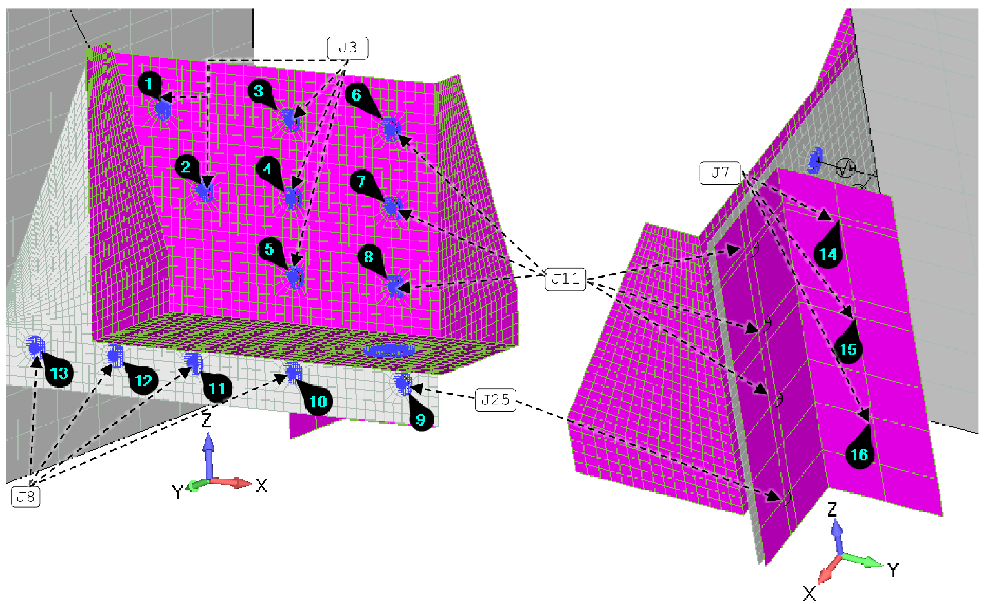
At joint J3, the extended rack-mount fitting transfers a maximum source limit demand of 211.43 lbf shear and 96.26 lbf tension. The reported minimum margin is +0.37 in tension.
→ PASS
→ PASS
Localized fastener failure / redistribution. The high forward-case load at AFT-gusset rivet No. 10 was redistributed to adjacent rivets 11–13 as a fail-safe sensitivity check. After redistribution, the source governing rivet demand is 240.23 lbf shear, with a reported minimum shear margin of +0.41.
→ PASS
→ PASS
Intercostal & Existing-Structure Interface
The FWD/AFT intercostal clips use MS20470AD4 rivets. The source maximum is 42.27 lbf shear and 1.61 lbf tension, giving a minimum reported shear margin of +4.33.
→ PASS
→ PASS
Doubler / OEM frame interface. The summed constraint demand at the 23-rivet doubler joint is 54.85 lbf maximum shear and 0.03 lbf maximum tension across the joint. The source assessment treats this as non-governing and concludes the redistributed loads remain within the existing structure’s substantiated capacity.
REFERENCES
Structural Methods & Allowables
- MMPDS-15 - Metallic Materials Properties Development and Standardization
- Analysis and Design of Flight Vehicle Structures - E. F. Bruhn
- Roark’s Formulas for Stress and Strain
- Aluminum Design Manual 2010
- Stress Analysis Manual - Air Force Flight Dynamics Laboratory, Wright-Patterson
- Fastener Design Manual - NASA Reference Publication 1228
Regulatory & Aircraft Load Basis
- Federal Aviation Regulations - 14 CFR Part 25
- DHC-8-100 Load Cases and Applied Loads
Fasteners & Hardware Data
- CherryMax Rivets technical data
- NAS528 Fastener Codes
- MS24694 technical data
- NASM3-20 aircraft-bolt technical data
Track & Fitting Data
- FE200744 stud-fitting technical data
- FE748-01-PD4 aircraft-track technical data
- ANCRA Aircraft Track technical data