Station-specific limit loads screened against emergency conditions.
INTRODUCTION
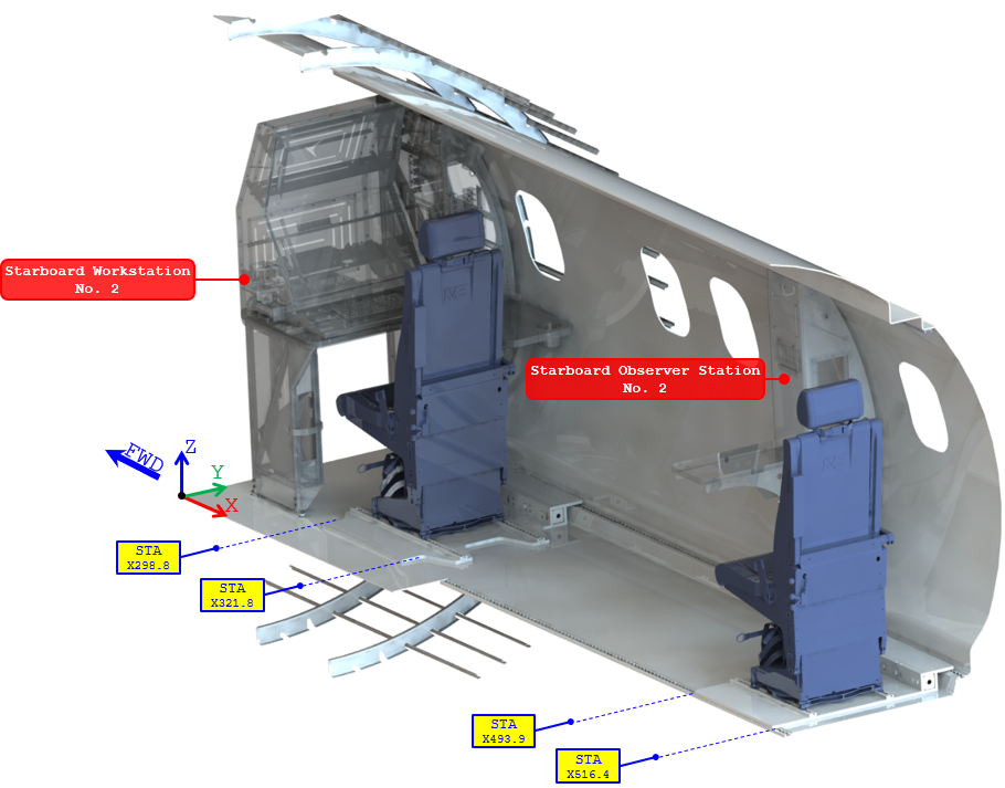
Static-strength substantiation of the Workstation and Observer Station seat-pallet assemblies and their installation on a DHC-8-100. The assessment covers governing flight and emergency loads, global FE response, seat-track strength, plate stresses, attachment reactions and fastener capacity.
The analysis compares calculated demand against aerospace material and joint allowables to demonstrate ultimate-strength compliance for the modified installations.
AircraftDHC-8-100Interior seat-pallet structural modification
InstallationsWSP + OSPPort / starboard mirrored arrangements
Assessment basisStarboard modelsOpposite-side installations covered by comparison
Substantiation routeFEM + classical checksSeat tracks, plates, attachments and fasteners
ENGINEERING SNAPSHOT
Beam/plate idealization with classical strength and stability substantiation.
Element geometry and plate resultants converted into fastener demand.
Seat tracks, plates, attachments and local fasteners satisfy the source checks.
DESIGN ASSESSMENT
Port and starboard layouts are identical and see the same vertical environment.
Port and starboard layouts are likewise identical with a common vertical load environment.
One model per pallet type captures the governing structural configuration without duplicating equivalent opposite-side analyses.
The corresponding port-side pallet is substantiated by comparison because its structural layout and applicable vertical loading are equivalent.
Governing-model decision
Model only the unique structural configurations. Mirrored port installations are covered by comparison rather than duplicating equivalent finite-element models.
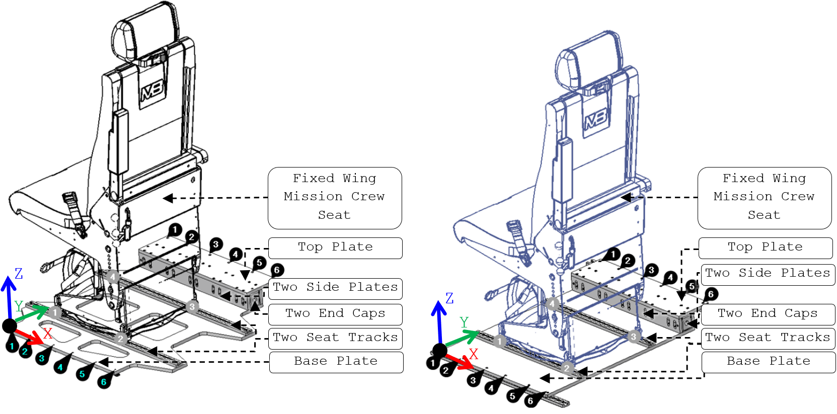
Seat Pallets Components
The pallets use machined/formed aluminum plates, thin-sheet end caps and extruded seat tracks. The table below retains the structural members, thicknesses and alloys used for substantiation.
Main structural components, thicknesses and materials.
| Component Name | Assembly | Thickness (in) |
Material |
|---|---|---|---|
| Base Plate | WSP | 0.5 | AL 7075-T651 Plate |
| OSP | |||
| Two Side Plates | WSP & OSP | AL 2024-T351 Plate | |
| Top Plate | |||
| Two End Caps | 0.05 | AL 2024-T3 CLAD Sheet | |
| Two Seat Tracks | 0.38 | AL 7075-T6 Extrusion |
Weight Estimation
Structure + concentrated payload
Only load-carrying pallet structure is modeled explicitly. Seat and occupant inertia are introduced at a combined center of gravity so payload stiffness is not credited to the structure.
Seat hardware allowance
The 55.9 lb seat weight is scaled by 1.15 to 64.3 lb to include omitted seat-related hardware; the occupant is modeled at 195 lb.
The seat and occupant are combined at an equivalent center of gravity using weight-weighted coordinates.
Payload idealization used in the finite-element models.
| Assembly | Total payload [lb] | CoG X [in] | CoG Y [in] | CoG Z [in] |
|---|---|---|---|---|
| WSP | 259.30 | 15.97 | 14.54 | 26.21 |
| OSP | 259.30 | 9.94 | 14.34 | 26.21 |
Modeling rationale. Non-structural hardware is excluded from the structural mesh; its mass effect is represented through the conservative payload idealization above. This keeps the FEM focused on the actual load-carrying pallet structure.
Material Properties
The following table lists the mechanical properties of the materials used in the WSP and OSP installations [MMPDS-15-Table 3.7.10.0(g1), Table 3.7.10.0(b2), Table 3.2.4.0(c1), Table 3.2.4.0(b2)].
Material allowables used for the Workstation and Observer Station seat-pallet installations.
AL 7075-T6 Extrusion t=0.25” – 0.499” |
AL 7075-T651 Plate t=0.5” – 1.0” |
AL 2024-T3 CLAD Sheet t=0.010” – 0.062” |
AL 2024-T351 Plate t=0.5” – 1” |
Unit | |
|---|---|---|---|---|---|
| Ftu | 81 | 77 | 60 | 63 | ksi |
| Fty | 73 | 70 | 44 | 48 | ksi |
| Fcy | 73 | 68 | 36 | 39 | ksi |
| Fsu | 43 | 44 | 37 | 37 | ksi |
| Fbru | 146 | 145 | 121 | 117 | ksi |
| Fbry | 113 | 117 | 82 | 90 | ksi |
| E x103 | 10.4 | 10.3 | 10.50 | 10.7 | ksi |
| Ec x103 | 10.7 | 10.6 | 10.70 | 10.9 | ksi |
| μ | 0.33 | 0.33 | 0.33 | 0.33 | - |
| ρ | 0.101 | 0.101 | 0.1 | 0.1 | lbm/in3 |
| G x103 | 4.0 | 3.9 | - | 4 | ksi |
| e | 7 | 7 | 12 or 15 | 8 | % |
Fasteners Allowables
Joint allowable philosophy
Use the weakest applicable failure path for the actual fastener / sheet stack-not the isolated fastener strength.
Sheet thickness and material can govern the joint.Countersunk geometry is checked with the applicable joint-strength reduction.Rivet tension is evaluated only where meaningful tensile reaction exists.
Fastener + sheet act together
Joint strength is controlled by compatibility between fastener strength, bearing resistance and local sheet geometry.
Local geometry matters
The countersink changes the effective load path and can reduce the usable static joint strength relative to an isolated fastener.
Critical thin layer
Where the non-countersunk sheet is thinner, its bearing capacity is compared directly against fastener/joint shear strength.
Shear-dominant rivet loading
Rivet tensile failure is not treated as governing unless the extracted reactions indicate a meaningful tensile component.
MS24694 Screws
MS24694 · Countersunk screws
Thread standardMIL-S-7742 · UNC-3A
MaterialCadmium-plated low-alloy steel
Material strengthFtu = 125 ksi · Fsu = 75 ksi
#8-32d = 0.164 in · Ptu = 1,750 lbf
#10-32d = 0.190 in · Ptu = 2,500 lbf
Design ruleUse the weakest applicable fastener / bearing path
Governing MS24694 shear/joint allowables retained from the source assessment.
| Screw | Application | Single-shear allowable [lbf] | Sheet-bearing path [lbf] | Governing allowable [lbf] |
|---|---|---|---|---|
| #8-32 MS24694-S11 | End caps to 2024/7075 plates | 1,580 | 992 | 992 · bearing |
| #10-32 MS24694-S51 / -S55 | Seat track to 7075-T651 base plate | 2,125 | 10,402 | 2,125 · screw shear |
Allowable basis. The #8 joint is governed by the thin 2024-T3 CLAD bearing path; the #10 seat-track joint is governed by screw single shear. Source values are based on the cited MMPDS and MS24694 data retained in the references.
LOAD CASES FORMULATION
REGULATORY SOURCE BASISFAR Part 25 structural-load criteria
Flight-load framework
FAR 25.321 and 25.331–25.351 are used with the aircraft load-case data to establish the flight envelope at each installation station.
Emergency landing
Emergency inertial factors are compared direction-by-direction with the extracted flight factors; the larger absolute limit value is retained for the FEM.
Load-Case Selection Rationale
WSP loads are screened at X312.35 and OSP loads at X508.17. Forward emergency loading governs longitudinally at 6.0 g; flight loads govern the vertical up/down cases. Aft loading is conservatively covered by the forward case.
Governing limit-load factors applied to the WSP and OSP finite-element models.
| Direction | WSP applied [g] | WSP basis | OSP applied [g] | OSP basis |
|---|---|---|---|---|
| Upward | 2.90 | Flight | 5.27 | Flight |
| Downward | 4.68 | Flight | 5.89 | Flight |
| Outboard | 2.00 | Emergency | 2.00 | Emergency |
| Inboard | 2.00 | Emergency | 2.00 | Emergency |
| Forward | 6.00 | Emergency | 6.00 | Emergency |
| Aft | Covered by Forward | Covered by Forward | ||
Ultimate-strength treatment. The source methodology applies the required 1.5 ultimate factor in the component margin calculations rather than multiplying the FEM limit loads before solution.
FINITE ELEMENT ANALYSIS (FEA)
MODEL
Load-Path Rationale
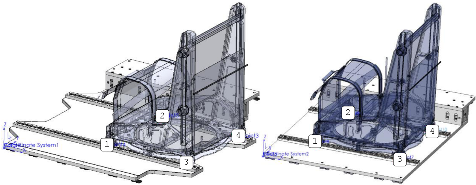
Seat/occupant inertia is introduced at the combined CoG through RBE3 distribution to the seat pins, then carried through the seat tracks and pallet plates into the ANCRA/NAS8604 interfaces and the aircraft OEM seat tracks.
Seat tracks
Beam elements retain the section properties governing axial and bending response.
Pallet structure
Base, side, top and end-cap panels use plate elements for membrane, bending and shear response.
CBUSH + merged joints
MS24694 screws use high-stiffness CBUSH translation with free rotations; selected NAS8604 plate joints use merged connectivity where local fastener stress is checked separately.
RBE3 + non-penetrating contact
RBE3s distribute payload without artificial stiffness; end-cap contact prevents penetration while allowing separation/sliding.
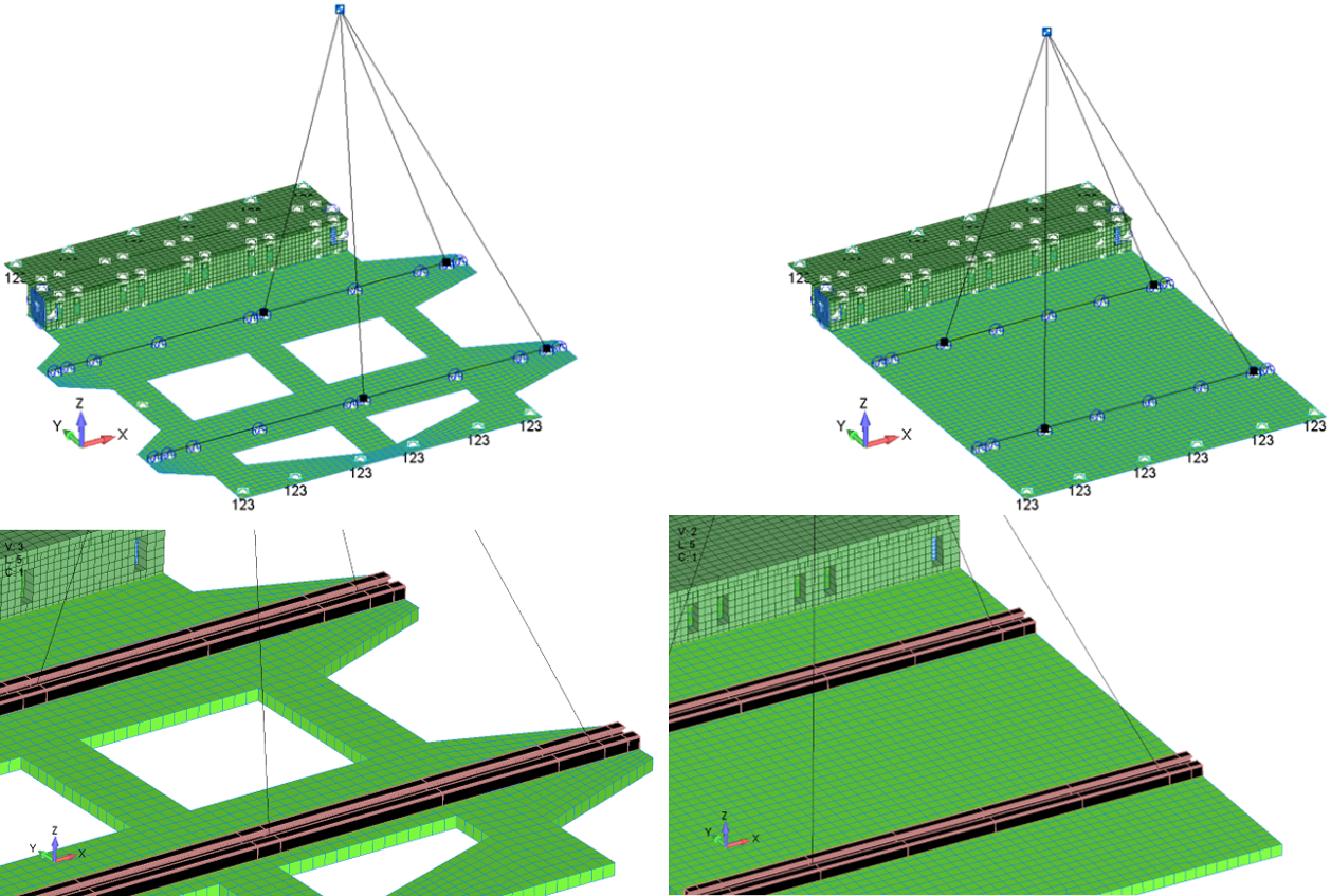
Idealization strategy
Preserve stiffness and load-path physics that govern strength; suppress non-critical holes/fillets and other detail that would add mesh cost without improving the global substantiation.
LOADS AND CONSTRAINTS
Five body-load directions are evaluated in FEMAP using the governing pallet-specific load factors.
BOUNDARY CONDITIONSInboard OEM track interface
Tx, Ty, Tz restrained.
Outboard OEM track interfaceTx, Ty, Tz restrained.
New seat-track endsTz restrained to represent vertical load transfer through base-plate contact.
Engineering rationale
Constraints are applied only at physical attachment/load-transfer locations. Full translational restraint at the OEM track interfaces prevents rigid-body motion, while the added vertical restraint at the new track ends represents contact-supported transfer into the base plate and surrounding aircraft floor structure.
ANALYSIS
Linear static solution is appropriate for the global strength response under the prescribed inertial load cases.
Mass and geometry are defined in a consistent English engineering unit system.
WTMASS enabled
Mass is entered in lbm, density in lbm/in³ and acceleration in in/s². WTMASS provides consistent mass-to-force conversion so solver forces are recovered in lbf and stresses in psi.
Analysis choice
The objective is static strength and load redistribution, not dynamic response. SOL 101 therefore provides the required global stress/reaction solution without adding unnecessary nonlinear or transient complexity.
FEM Results
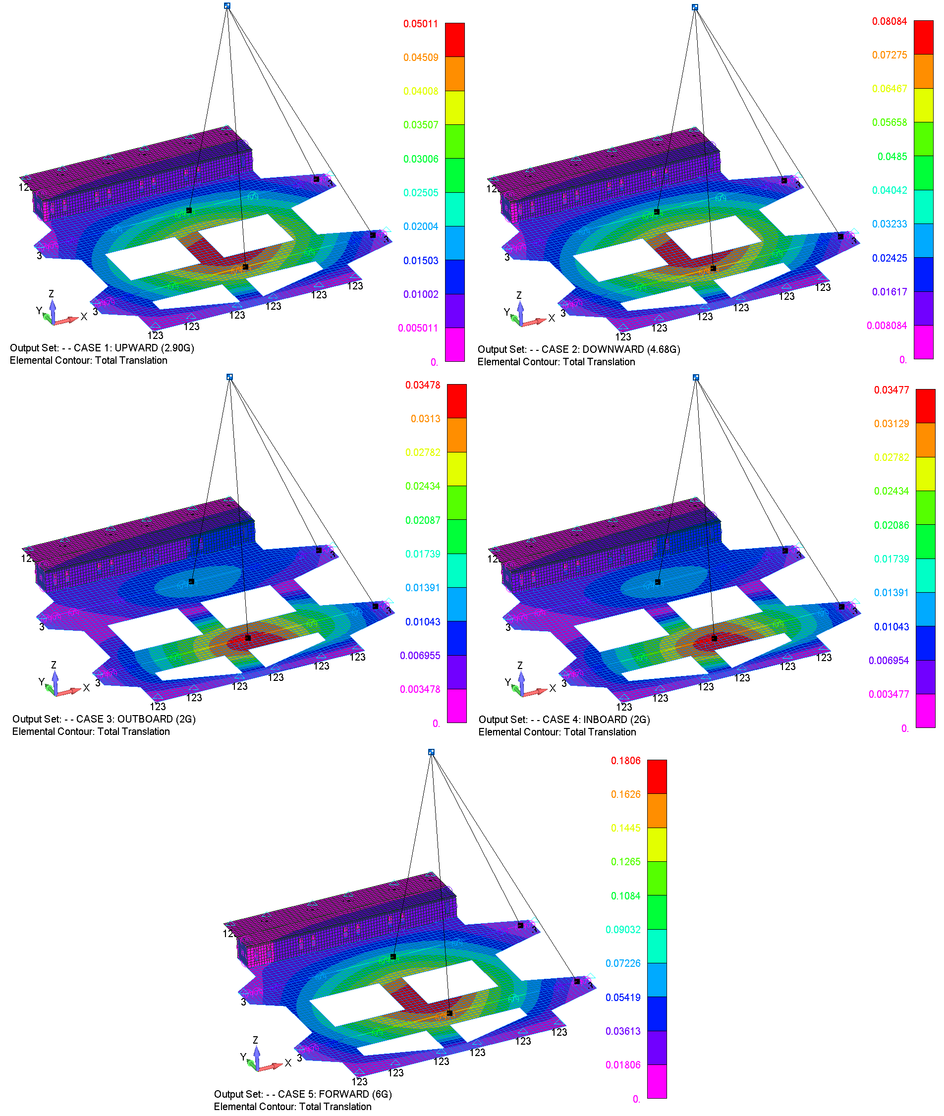
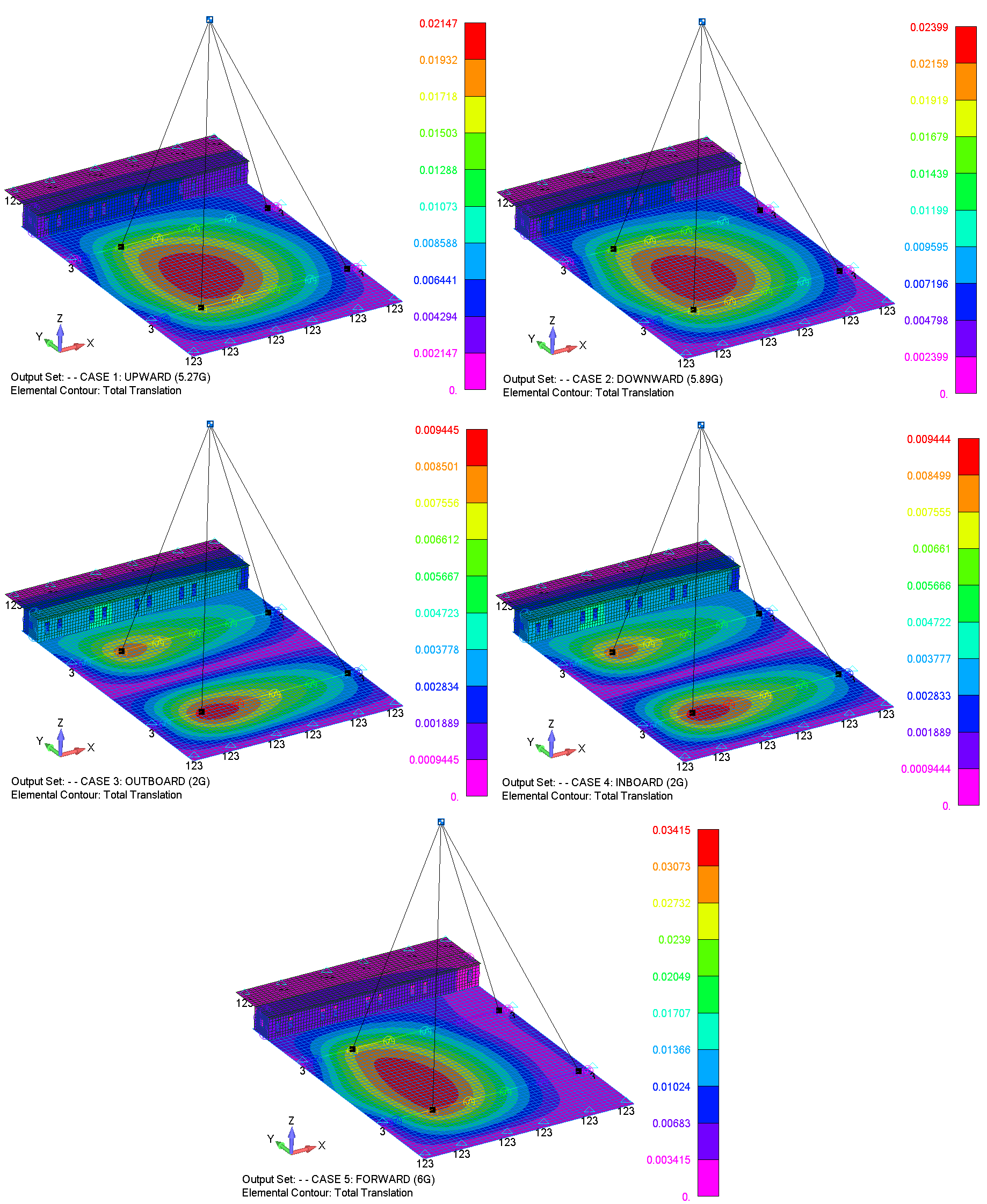
Total Translation Contours
the associated figures illustrate the Total Translation Contours (in inches) for the WSP and OSP installations, respectively.
Seat Tracks
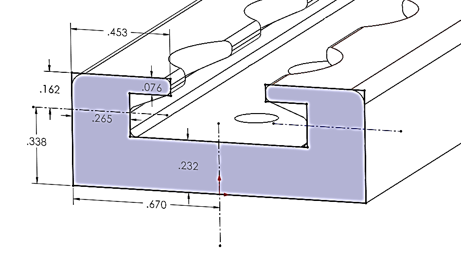
Seat tracks are modeled as beam elements using the actual section properties. Axial force and biaxial bending are combined element-by-element so extrema from unrelated locations are not artificially combined.
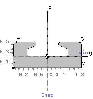
Seat-track section properties used in the FE model.
| Property | Value | Unit |
|---|---|---|
| Area, A | 0.490593 | in² |
| Izz | 0.091901 | in⁴ |
| Iyy | 0.010491 | in⁴ |
| Extreme fiber, +y / −y | +0.670 / −0.670 | in |
| Extreme fiber, +z / −z | +0.287 / −0.213 | in |
Element-by-element stress recovery
Beam-end axial and bending terms are combined at the same physical element/end. This preserves the real load path and avoids pairing unrelated global maxima.
Combined beam stress
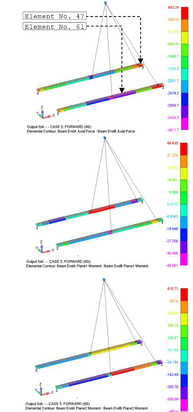
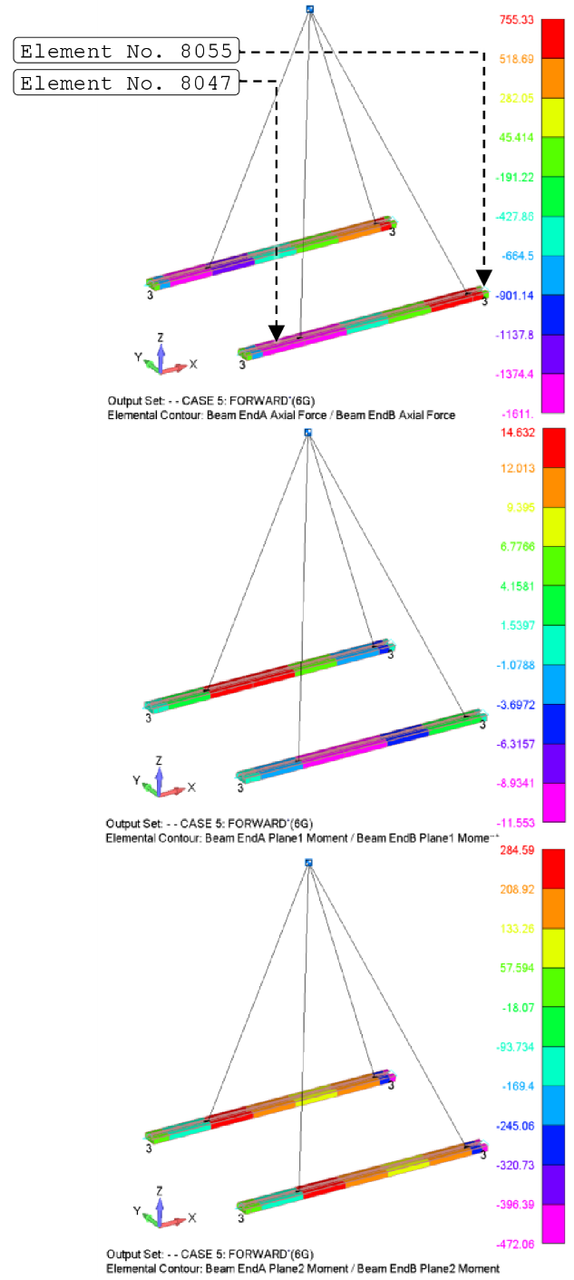
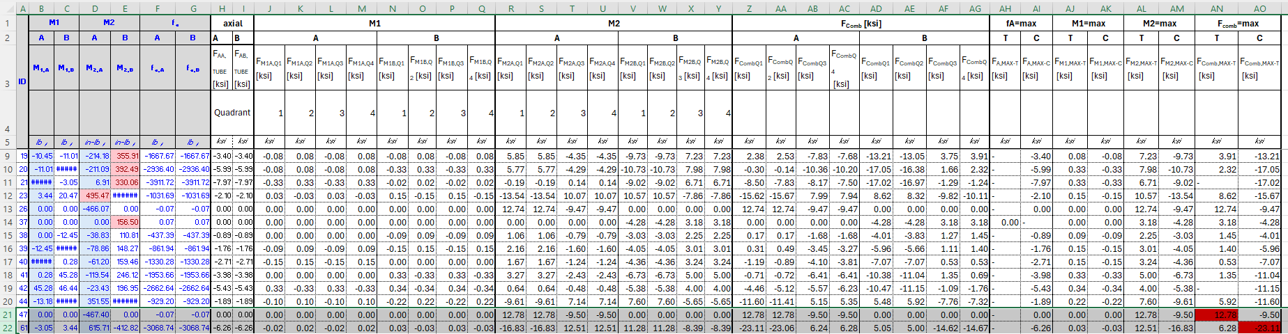
Governing seat-track demands and recovered combined stresses.
| Assembly | Governing element | Load case | Axial force [lbf] | Largest listed bending moment [in-lbf] | Max tension [ksi] | Max compression [ksi] |
|---|---|---|---|---|---|---|
| WSP | 61 | Forward | −3,068.74 | 615.71 | 12.78 | −23.11 |
| OSP | 8047 | Forward | −1,611 | 316.07 | 12.90 | −12.01 |
For AL 7075-T6 extrusion, Ftu = 81 ksi and Fcy = 73 ksi. With the 1.5 ultimate factor, the governing seat-track margin is compression.
Flange Crippling
The thin-walled seat-track section is checked for local crippling using the Needham/Gerard angle-element method. The cross-section is decomposed into angle elements and their crippling capacities are summed using the source methodology.
| Angle | An | Ce | Fccn [ksi] | AnFccn |
|---|---|---|---|---|
| 1 | 0.047 | 0.342 | 104.46 | 4.882 |
| 2 | 0.234 | 0.366 | 178.22 | 41.677 |
| 3 | 0.234 | 0.366 | 178.22 | 41.677 |
| 4 | 0.047 | 0.342 | 104.46 | 4.882 |
The resulting seat-track crippling allowable is 165.93 ksi. Using the governing 23.11 ksi compressive demand:
Column Buckling
Column stability is checked using the source Euler-type formulation:
Effective column definition. The seat tracks are attached to the base plate through 10 screws on the WSP and 8 on the OSP. The source assessment uses the pinned-pinned case with K = 1 and n = 9 / 7, respectively.
Seat-track column-buckling results.
| Assembly | Critical buckling stress [ksi] | Governing compressive demand [ksi] |
|---|---|---|
| WSP | 178.64 | 23.11 |
| OSP | 209.186 |
Structural Sheet Metals
Plate strength is screened using major/minor principal stresses on both shell faces. Tensile demand is compared with Ftu and compressive demand with Fcy. The compact table below retains the governing source values rather than every intermediate contour extraction.
Governing principal-stress magnitudes recovered from the WSP and OSP plate models.
| Assembly | Material / thickness | Max tension [ksi] | Max compression [ksi] | Governing case |
|---|---|---|---|---|
| WSP | AL 7075-T651 · 0.5 in | 18.51 | 17.78 | Forward |
| AL 2024-T3 CLAD · 0.05 in | 14.02 | 11.82 | Forward | |
| AL 2024-T351 · 0.5 in | 22.14 | 17.11 | Forward | |
| OSP | AL 7075-T651 · 0.5 in | 9.66 | 9.26 | Forward |
| AL 2024-T3 CLAD · 0.05 in | 1.34 | 2.22 | Mixed | |
| AL 2024-T351 · 0.5 in | 7.43 | 4.97 | Forward |
AL 7075-T651 Plate
The AL 7075-T651 base/top plate check uses Ftu = 77 ksi and Fcy = 68 ksi. The WSP forward case governs this material family with 18.51 ksi tension and 17.78 ksi compression.
The Attachment Points
NAS8604-7 attachment reactions are resolved into resultant shear and tensile demand. The recruiter version retains the governing source check instead of the full node-by-node reaction tables.
Governing attachment-bolt demand used in the source substantiation.
| Joint | Load case | Shear demand [lbf] | Tensile demand [lbf] | Shear allowable [lbf] | Tensile allowable [lbf] |
|---|---|---|---|---|---|
| WSP NAS8604-7 attachment | Forward | 1,110.15 | 254.65 | 4,660 | 2,250 |
The source joint check includes the 1.5 ultimate factor and 1.15 fitting factor:
Seat Pallets’ Fasteners
NAS8604-17 top-plate screws
Plate resultants are converted to element-edge forces using extracted mesh geometry, then resolved into screw shear/tension demand.
Single-fastener screening
Where a local maximum is compared against one screw capacity, the assumption intentionally avoids crediting redistribution across the full fastener group.
Seat pins → track → base plate
Rigid-body reactions at the four seat pins provide the input for the MS24694 seat-track attachment check.
Certified seat pins
Seat pins supplied with the certified seat are accepted for the emergency-load application; the pallet-side fasteners remain explicitly checked.
NAS8604 Bolts
NAS8604 Bolts were utilised in three locations within the WSP and OSP:
Connecting the Base plate to the OEM Seat Track
Connecting the Side Plates to the Top Plate.
Connecting the Side Plates to the Base Plate.
NAS8604 Bolts utilized in Side Plates – Top Plate Joint.
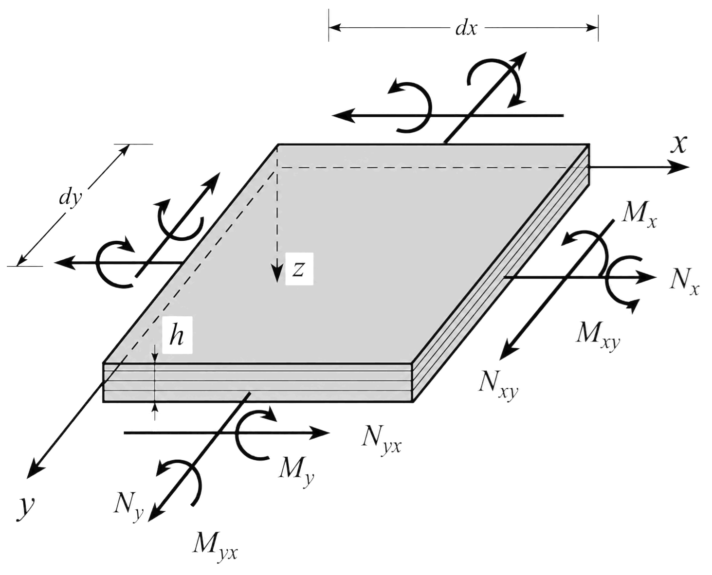
The top plate is attached to the side plates with 20 NAS8604-17 screws. FEMAP plate resultants are converted to element-edge forces and screened across every load case using a Python post-processing workflow.
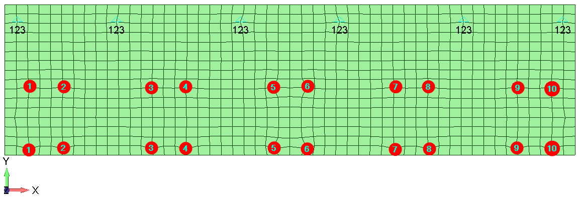
Python automates FEMAP plate-resultant post-processing so every valid element and load case is screened with the same calculation sequence.
- Read FEMAP-exported nodal coordinates and plate resultants.
- Reconstruct quadrilateral element geometry and local dimensions.
- Convert membrane/shear resultants into element-edge forces.
- Screen all load cases and export the governing shear/tension demand.
Why automate?The governing fastener demand can occur in an element that does not contain the largest individual plate-force component. Automated screening preserves a repeatable, traceable search across the complete result set.
Governing Python-recovered demand for the top-plate fasteners.
| Assembly | Load case | Max screw-direction shear [lbf] | Max tensile demand [lbf] |
|---|---|---|---|
| WSP | Forward | 881.80 | 189.41 |
| OSP | Forward | 290.96 | 61.06 |
Fastener screening. NAS8604-17 ultimate capacities are 4,660 lbf in shear and 4,480 lbf in tension. Even the conservative single-fastener WSP demand remains below both capacities.
MS24694 Screws utilized in Seat Track – Base Plate Joint.
The new seat tracks are attached to the base plate with MS24694-S51/-S55 screws. Seat-pin reactions transfer the seat/occupant inertia into the track; the source assessment conservatively screens the maximum resultant pin shear and axial demand against the screw/joint allowables.
Governing seat-pin demand retained from the source assessment.
| Assembly | Governing case | Max shear [lbf] | Max axial/tension magnitude [lbf] |
|---|---|---|---|
| WSP | 6 g Forward | 389.23 | 1,415.67 |
| OSP | 6 g Forward | 389.23 | 1,418.71 |
Load-path treatment. OEM seat pins are accepted as part of the certified seat. The structural installation check focuses on the new track/base-plate screws carrying the recovered seat reactions.
REFERENCES
Structural Methods & Allowables
- MMPDS-15 - Metallic Materials Properties Development and Standardization
- Stress Analysis Manual - Air Force Flight Dynamics Laboratory, Wright-Patterson AFB
Regulatory & Aircraft Load Basis
- Federal Aviation Regulations - 14 CFR Part 25
- FAA Advisory Circular AC 120-27D - Aircraft Weight and Balance Control
- DHC-8-100 Load Cases and Applied Loads
Fasteners & Hardware Data
- Fastener Design Manual - NASA Reference Publication 1228
- MS24694 screw technical data
Track & Fitting Data
- ANCRA Aircraft Track technical data
- 42182-10 ANCRA flush seat-track fitting data
SUBSTANTIATION OUTCOME
Starboard models substantiate the mirrored port installations by comparison.
Combined stress, crippling and column-buckling checks satisfy the source assessment.
Principal-stress and attachment reaction checks remain within the applicable allowables.
NAS8604 and MS24694 fastener demands are below the governing shear/tension or joint allowables.