Protects mission radar/communications equipment while maintaining the required external contour and low signal attenuation.
INTRODUCTION
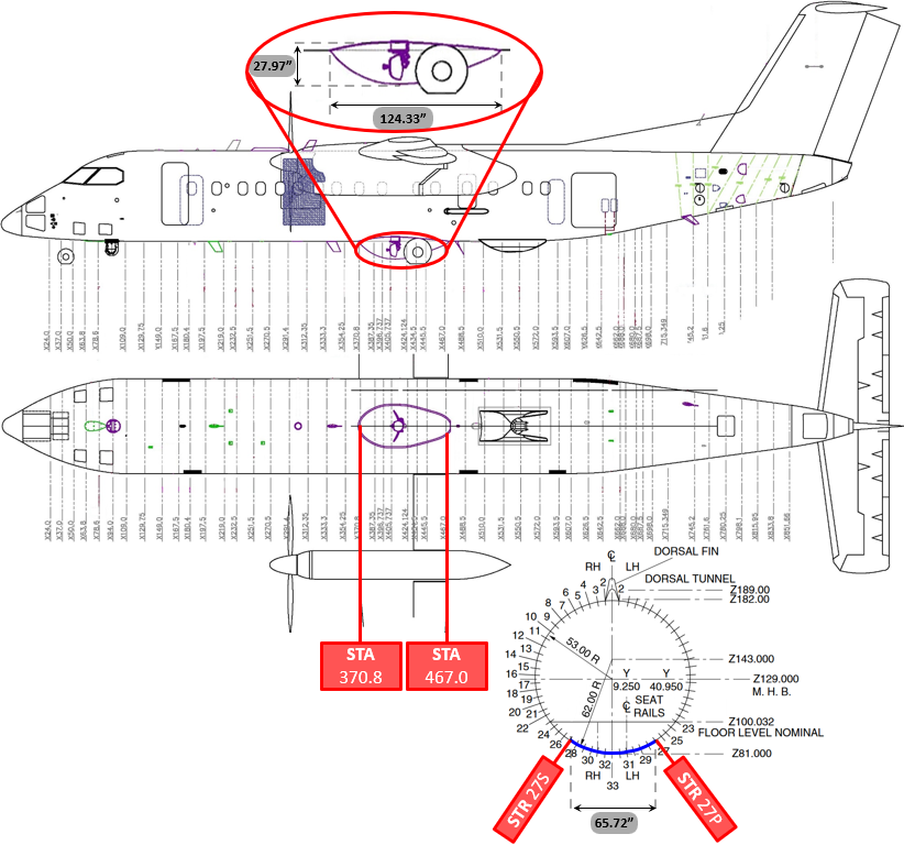
Static-strength substantiation of the DHC-8-100 mission-radar radome installation, with emphasis on the custom fiberglass flange that transfers external aerodynamic demand into the aircraft lower fuselage.
The assessment combines conservative aerodynamic idealization, composite joint allowables, 3D rigid-body fastener load distribution, Classical Laminate Plate Theory (CLPT), and local interface shear checks.
AIRCRAFTDHC-8-100Mid-fuselage external radome
PRIMARY INTERFACE16-ply fiberglass flangeMeasured cured thickness: 0.192 in
LOAD PATHAerodynamics → Attachments → FlangeEight-bolt bounding reaction model
SUBSTANTIATIONJoints + CLPT + ShearPositive margins / inspection checks
DESIGN ASSESSMENT
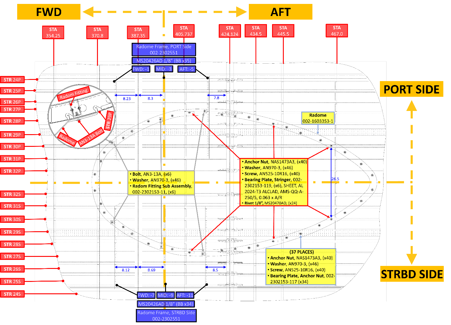
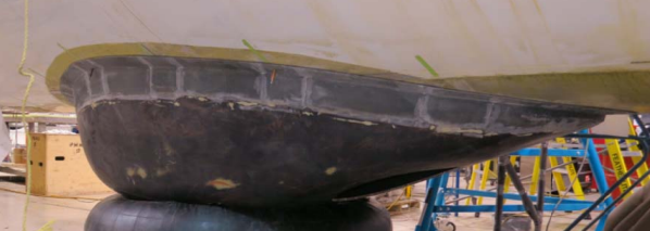
In-house fiberglass laminate bridges the supplier radome to the aircraft lower skin and spreads attachment load around the perimeter.
Transfers local attachment reactions between the radome installation and surrounding fuselage structure.
Receive the remaining installation loads through the fitting architecture.
LOAD-PATH RATIONALE
Separate global aerodynamic demand from local composite-interface checks.
External lift and drag enter through the radome shell, resolve into perimeter attachment reactions, pass through the custom fiberglass flange as in-plane bearing and out-of-plane pull-through demand, and then transfer into the aircraft lower-skin/frame structure. Treating the global aerodynamics, discrete fastener reactions and local laminate response as separate calculation stages keeps the load path traceable while avoiding unnecessary detail in any one model.
External lift and drag enter through the radome shell, resolve into perimeter attachment reactions, pass through the custom fiberglass flange as in-plane bearing and out-of-plane pull-through demand, and then transfer into the aircraft lower-skin/frame structure. Treating the global aerodynamics, discrete fastener reactions and local laminate response as separate calculation stages keeps the load path traceable while avoiding unnecessary detail in any one model.
ENGINEERING RATIONALECustom flange used as the integration bridge
The flange provides a continuous load-spreading interface between the commercially supplied radome and the aircraft lower skin, while accommodating manufacturing tolerance, alignment and environmental sealing requirements.
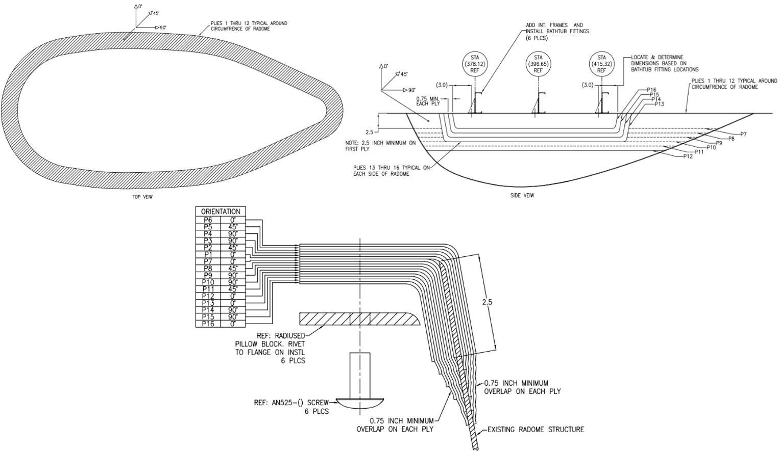
CURED THICKNESS0.192 in
REINFORCEMENTFiberglass Style 7781MIL-C-9084
MATRIXEPOCAST 50A + 9816Manufacturer mixing/cure schedule
LAYUP16 plies0/45/90/90/45/0/0/45/90/90/45/0/0/90/90/0°
MATERIAL-SELECTION RATIONALE
Fiberglass supports the electromagnetic function of the radome
The source identifies favorable dielectric behavior as a key integration benefit: the flange provides structural continuity without introducing the radar attenuation concerns associated with a metallic interface.
MATERIAL PROPERTIES
Hot-wet strength set
Because the fabrication condition is unknown, the source adopts the conservative 160°F / 95% RH condition as the laminate strength basis.
Additional 25% knockdown
The already conservative source allowables are reduced a further 25% to account for manufacturing and final-laminate uncertainty.
Ftu132.11 ksi
Ftu225.75 ksi
Fcu136.14 ksi
Fcu236.14 ksi
Fsu128.44 ksi
Strength basis: [Analysis & Design of Composite & Metallic Flight Vehicle Structures by Richard Abbott], aligned by the source with the lower bound of MIL-HDBK-17-2F.
6.5 ksi typical → 4.875 ksi design value
The source treats glass/epoxy interlaminar shear as comparable to a carbon laminate using the same resin and then applies the same 25% uncertainty reduction to the 6.5 ksi typical value.
Lower-bound manufacturing sensitivity retained
ILSS is sensitive to cure quality and laminate processing. Using the knocked-down value deliberately avoids crediting a best-case fabrication state that is not documented.
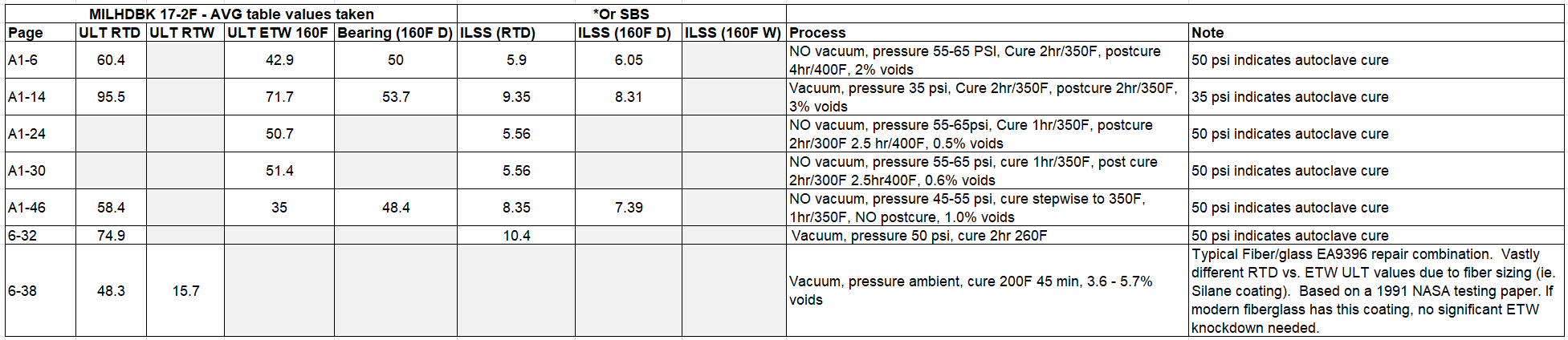
The source data below shows ILSS values spanning approximately 5.5–10.4 ksi; the adopted 4.875 ksi value remains below that range after the explicit uncertainty reduction.
JOINTS ALLOWABLE
Composite-joint capacity is treated as a failure-mode problem rather than an isolated fastener-strength check. The governing allowable is taken from the weakest applicable mechanism for the actual fastener/laminate geometry.
Joint allowable philosophy
Separate the in-plane and out-of-plane load paths, then govern each with the minimum applicable capacity.
COMPOSITE-JOINT METHODOLOGY
Stay inside the demonstrated test envelope.
The baseline glass-laminate bearing value is not used blindly. Thickness-to-diameter, edge-distance-to-diameter, fastener diameter and reference-laminate thickness are checked first; only the applicable knockdowns are then carried into the joint allowable. This prevents the analysis from crediting bearing strength that is unsupported by the cited test configuration.
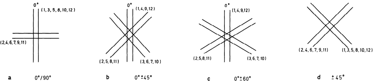
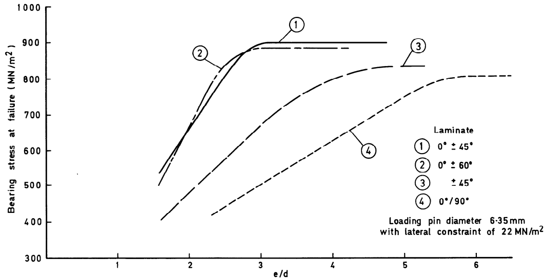
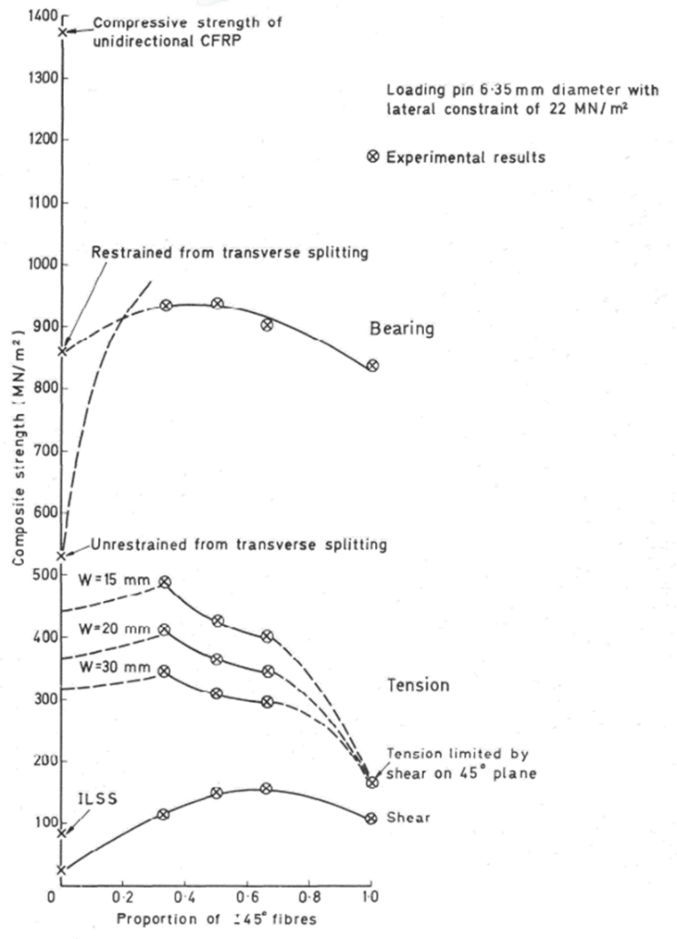
The source identifies five variables that control single-hole composite bearing response: [The Strength of Bolted Joints in Multidirectional CFRP Laminates – Section 7.2].
Lateral constraintControls local splitting / bearing restraint.
Ply orientationChanges the local load-carrying directions.
0° : ±45° contentInfluences bearing and shear-dominated response.
Stacking sequenceChanges the local through-thickness failure path.
Laminate thicknessDrives D/t sensitivity and bearing capacity.
Joint’s Bearing Strength:
GLASS-FIBER BASELINEFbru = 40 ksiWorst-environment general value from the source methodology.
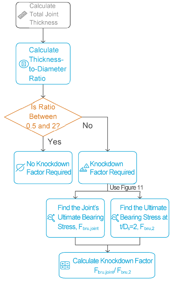
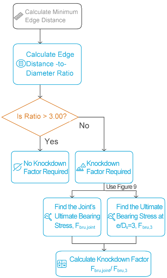
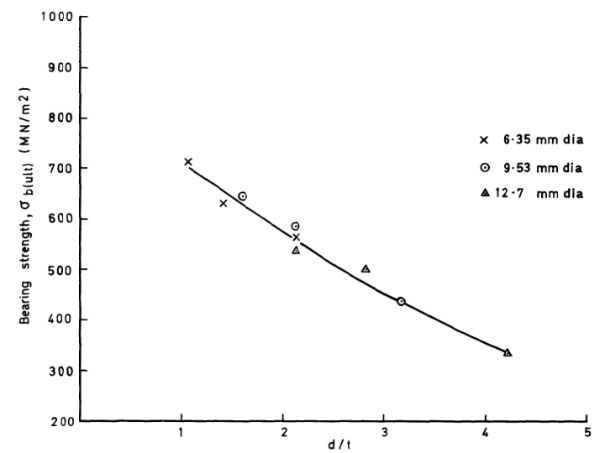
Geometry window0.5 ≤ t/D ≤ 2e/D > 3.0
If outside the windowUse source-chart knockdownsScale for smaller fastener diameter / thinner laminate when applicable
MODELING RATIONALEDo not credit composite bearing strength beyond the test envelope.
The source uses chart-based knockdowns when geometry departs from the published test configuration. This keeps the allowable tied to demonstrated behavior rather than extrapolating full 40 ksi bearing strength into a less favorable joint. [Analysis & Design of Composite & Metallic Flight Vehicle Structures by Richard Abbott- Section 12.2.4.2].
The published knockdown charts below are based on 0/±45° tested laminates. Applying them to the present laminate is conservative because the installed layup also contains 90° reinforcement, which adds a load-carrying direction not credited by those charts.
Joint’s Pull-Through Strength:
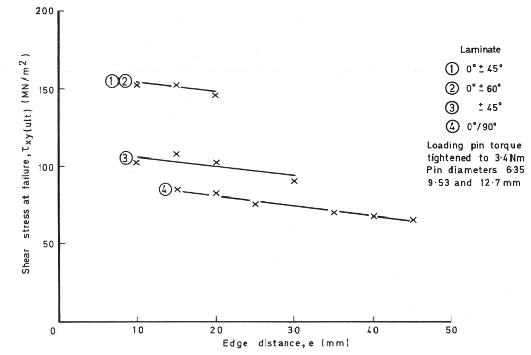
No fully analytical pull-through solution is credited for the laminated joint. The source therefore uses a conservative semi-empirical method correlated to interlaminar shear strength [Analysis & Design of Composite & Metallic Flight Vehicle Structures by Richard Abbott]. A reinforcement factor of 0.75 is applied for glass fiber.
Laminate thickness
Bolt shank diameter
Bolt head / washer diameter
Interlaminar shear stress
Reinforcement factor: 1.0 carbon, 0.75 glass
The source curves show a minimum shear strength at failure of 22 ksi and an ILSS value of 12.29 ksi. The analysis intentionally retains the lower knocked-down value established above: 4.875 ksi.
AN3-13A and AN525-10R16 Fasteners
AN3-13A and AN525-10R16 fastener properties [Technical Data Sheet-NASM3-20, NASM525].
| P/N | Type | Head | Size (Callout)(Thread)(Length) |
Material | Ds (in) |
(Fsu)(Ftu) for fastener material [ksi] |
(fsu)(ftu) for fastener in single shear [lbf] |
Thread Standard |
|---|---|---|---|---|---|---|---|---|
| AN3-13A | Aircraft Bolt | Hex | (#10‑32)(UNF‑3A)(1.40625) | Non-Corrosion Resistant Steel | 0.19 | N/R | (2125)(2210) | MIL-S-7742 |
| AN525-10R16 | Screw | Recessed | (#10-32)(UNF-3A)(1) | Cadmium Plated Alloy Steel | 0.19 | (0.6x125)(125) | MIL-S-7742 |
AN3-13A Fastener:
AN3-13A - in-plane capacity
Fastener single-shear capacity: 2,125 lbf. The composite bearing check below establishes whether the laminate reduces the usable joint capacity.
The total accumulated thickness of the laminate is t= 0.192 in.
tjoint/Ds=0.192/0.19=1.01 → No knockdown factor is required.
The total flange width is 2.70 inches. Hence, the estimated edge distance of the utilized fasteners is e=2.7/2=1.35 in. Conservatively, the edge distance is further reduced by 50%.
e/Ds=0.675/0.19=3.55 → No knockdown factor is required.
The shank diameter is 0.19 in → a knockdown factor is required.
The knockdown factor is 0.19/0.25=0.76.
The overall thickness of the tested laminate is 0.118 in. Our incorporated laminate is 0.192 in thick; thicker than the tested laminate. This will increase the failure bearing stress. For conservatism, this minimum value is used.
After the 0.76 diameter knockdown, Fbru = 30.40 ksi and the laminate bearing capacity is 1,109 lbf. Bearing therefore governs the AN3-13A in-plane joint allowable.
AN3-13A - out-of-plane capacity
Fastener tensile capacity: 2,210 lbf. Pull-through of the laminate/washer interface is checked next.
The utilized AN970-3 washer has an outer diameter value of 0.875 in [Technical Data Sheet-AN970-3 Washer]. Therefore, the joint’s Pull-Through Strength can be calculated as below:
The calculated pull-through capacity is lower than fastener tension, so 1,634.65 lbf governs the out-of-plane joint allowable.
AN525-10R16 - fastener material capacities
Based on the table below, the AN525-10R16 Fastener is made from Cadmium Plated Alloy Steel which has an Ultimate Shear and Tensile Strength values of Fsu=0.6x125=75 ksi [Fastener Design Manual-NASA Reference Publication 1228-Page 21] and Ftu=125 ksi [Technical Data Sheet-NASM525]. Considering the fastener cross-sectional area, the Ultimate Shear and Tensile Loads can be calculated as below:
is based on nominal shank diameter; is based on the minimum external-thread minor diameter.
The Joint Bearing strength will be the same as calculated before, namely fbru=1,109 lbf. Since the Ultimate Shear Load is greater than the Joint Bearing Load, the later will be considered as the in-plane joint allowable.
Moreover, the screw’s Pull-Through Strength will be the same as calculated before, namely fpull=1,635 lbf. Since the Ultimate Tensile Load is greater than the Pull-Through Strength, the later will be considered as the out of plane joint allowable.
Summary
Both attachment types are governed by the same composite interface capacities, summarized below.
Governing ultimate joint capacities.
| Joint | In Plane Strength [lbf] |
Out of Plane Strength [lbf] |
|---|---|---|
| AN3-13A Fasteners’ Joints | 1,109 | 1,634.65 |
| AN525-10R16 Fasteners’ Joints | 1,109 | 1,634.65 |
LOADS
IDEALIZATIONInverted 2D wingRadome fairing treated as a downward-lift surface.
SEA-LEVEL DENSITYρ = 0.00238 slug/ft³
MAX OPERATING SPEEDVMO,max = 242 kt408.45 ft/s
AERODYNAMIC CENTER1/3 chordMid-height in z
LOAD-CASE SELECTION RATIONALE
Bound the external installation with the most adverse aerodynamic operating condition used by the source.
The assessment uses sea-level density and maximum operating speed, conservatively sets the radome lift coefficient equal to the aircraft-wing cruise value, applies the cited maximum drag coefficient, and converts both aerodynamic forces to ultimate demand with a 1.5 factor. Level fuselage attitude is retained for the downward-lift bound because increasing positive angle of attack reduces the effective lift of the inverted fairing, while a significant negative fuselage angle is not considered attainable.
The assessment uses sea-level density and maximum operating speed, conservatively sets the radome lift coefficient equal to the aircraft-wing cruise value, applies the cited maximum drag coefficient, and converts both aerodynamic forces to ultimate demand with a 1.5 factor. Level fuselage attitude is retained for the downward-lift bound because increasing positive angle of attack reduces the effective lift of the inverted fairing, while a significant negative fuselage angle is not considered attainable.
AERODYNAMIC RATIONALEUse the aircraft-wing cruise lift coefficient as a conservative radome upper bound.
The source assumes the radome cannot be more aerodynamically efficient than the aircraft wing. The wing cruise coefficient is therefore used directly as the maximum radome lift coefficient, then the resulting force is converted to ultimate with a 1.5 factor.
Radome fairing dimensions and assumed aerodynamic-center location.
Aerodynamic Center (in) |
Dimensions (in) |
||||
|---|---|---|---|---|---|
| Xc.g. | Yc.g. | Zc.g. | L | W | D |
| 41.33 | 0 | -13.985 | 124.33 | 65.72 | 27.97 |
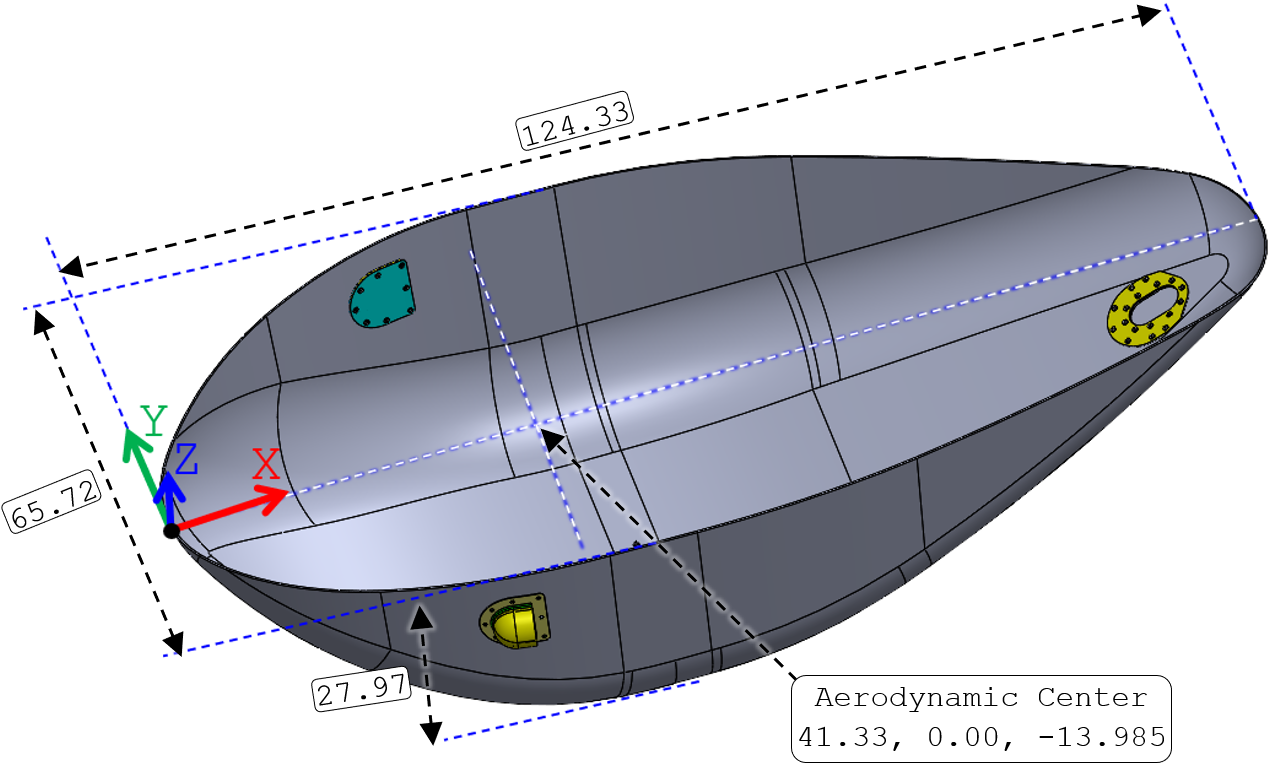
Horizontal fuselage attitude governs the inverted fairing
The source treats increased positive fuselage angle of attack as reducing the fairing’s effective lift. A significant negative fuselage angle is not considered attainable; level orientation therefore bounds the downward-lift case.
CD,max = 0.051
Maximum radome drag coefficient is taken from the cited Horner drag data [Fluid-Dynamic Drag-Horner, page 8-5, Fig. 11].
The wing cruise lift coefficient is first established from aircraft lift equilibrium:
Using the radome planform and the source planform factor of 0.6:
The same dynamic-pressure basis is applied to drag using :
ULTIMATE AERODYNAMIC LOADSBounding global demand
Downward lift 2,916.99 lbf
Drag 193.87 lbf
Factor 1.5
STATIC ANALYSIS
Fasteners' Reaction Forces
BOUNDING ATTACHMENT MODELCredit only eight extreme attachment bolts.
Aerodynamic force and moment are reacted at selected FWD, starboard, AFT and port extreme locations using 3D rigid-body analysis. Concentrating the global load into this sparse attachment set is intentionally conservative relative to distributing it around the full perimeter.
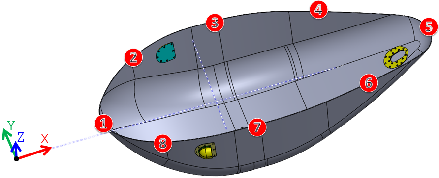
Shear and axial reactions [lbf] at the assumed main attachment points.
| Fastener No | Coordinates | fx | fy | fz | Shear | Axial |
|---|---|---|---|---|---|---|
| 1 | 0, 0, 0 | -34.2 | 0.0 | 461.2 | 34.2 | 461.2 |
| 2 | 17.47, 16.43, 5 | -24.2 | 0.0 | 426.5 | 24.2 | 426.5 |
| 3 | 34.94, 32.86, 10 | -14.3 | 0.0 | 391.7 | 14.3 | 391.7 |
| 4 | 79.63, 16.43, 5 | -24.2 | 0.0 | 302.8 | 24.2 | 302.8 |
| 5 | 124.33, 0, 0 | -34.2 | 0.0 | 213.8 | 34.2 | 213.8 |
| 6 | 79.63, -16.43, 5 | -24.2 | 0.0 | 302.8 | 24.2 | 302.8 |
| 7 | 34.94, -32.86, 10 | -14.3 | 0.0 | 391.7 | 14.3 | 391.7 |
| 8 | 17.47, -16.43, 5 | -24.2 | 0.0 | 426.5 | 24.2 | 426.5 |
GOVERNING ATTACHMENT DEMANDExtreme-bolt reaction
Max shear 34.2 lbf
Max axial 461.2 lbf
PASS
Flange
Classical Laminate Plate Theory
The 16-ply flange is represented through the ABD stiffness matrix, with ply-level direct, bending and total stresses recovered through the laminate.
Tsai-Wu · Hill · Hoffman
The source spreadsheet compares ply stresses against multiple composite failure criteria, allowing the minimum margin to identify the governing interaction.
The flange input is taken at the attachment location with the highest applied load. The governing row is highlighted below.
Applied force [lbf] and moment [in-lbf] at each assumed attachment; is applied at the 2.7 in outer flange edge. The highlighted row represents the governing attachment demand.
Location No |
fx | Moment (My) due to fz |
|---|---|---|
| 1 | 34.2 | 461.2x2.70=1,245.24 |
| 2 | 24.2 | 426.5 x2.70=1,151.55 |
| 3 | 14.3 | 391.7 x2.70=1,057.59 |
| 4 | 24.2 | 302.8 x2.70=817.56 |
| 5 | 34.2 | 213.8 x2.70=577.26 |
| 6 | 24.2 | 302.8 x2.70=817.56 |
| 7 | 14.3 | 391.7 x2.70=1,057.59 |
| 8 | 24.2 | 426.5 x2.70=1,151.55 |
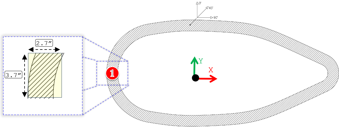
❶ · X · Y · 3.7” · 2.7”
CRITICAL-ELEMENT RATIONALEAnalyze the flange where local attachment demand is highest.
A 3.7 × 2.7 in plate element at the leading edge is isolated because that location carries the governing fastener reaction. Drag and the attachment moment are converted into running loads over the element dimensions for CLPT input.
The following outputs document the laminate definition and ABD stiffness, followed by ply-level stress recovery and the governing failure-criterion margin.
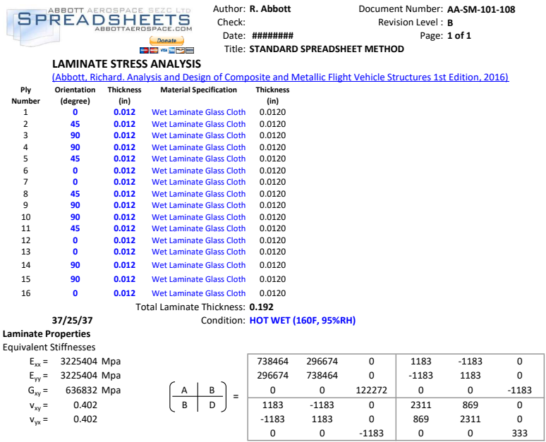
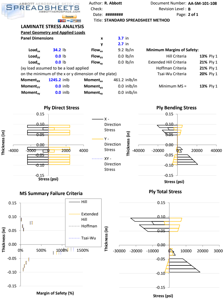
FLANGE GOVERNING RESULTHill criterion
Minimum margin 13%
Material knockdown 25%
PASS
The reported positive margin is obtained after the 25% laminate-property knockdown used to cover source manufacturing uncertainty.
A local 2.5 × 2.5 in interface element is then used to resolve the combined lift/drag shear transferred between the radome and flange.
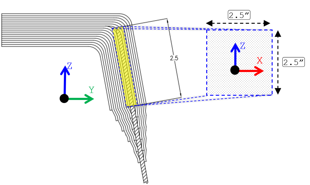
2.5” · 2.5” · X · Z · Y · Z
The resultant shear is converted to average interface shear stress over the selected area:
Interface shear - PASS5.45 psi demand versus 270 psi minimum EPOCAST 50-A1 lap-shear strength [Epocast 50-A1 Resin - Hardener 9816].
All other structural components
INSPECTION CHECKRemaining fitting and frame structure
The source closes the remaining components by inspection because the attachment tension and shear reactions are low; consequently, the loads passed through the tension-fitting sub-assembly into the radome frames are also small.
PASS BY INSPECTION
REFERENCES
Composite Materials & Analysis Methods
- Composite Materials Handbook - MIL-HDBK-17 / CMH-17
- Analysis & Design of Composite & Metallic Flight Vehicle Structures - Richard Abbott
- The Strength of Bolted Joints in Multidirectional CFRP Laminates
Joint & Fastener Data
- Fastener Design Manual - NASA Reference Publication 1228
- NASM3-20 technical data
- NASM525 technical data
- AN970-3 Washer technical data
Aerodynamic Load Basis
- Fluid-Dynamic Drag - S. F. Horner
Composite Fabrication & Material Data
- MIL-C-9084 - Style 7781 fiberglass fabric specification
- EPOCAST 50-A1 / Hardener 9816 manufacturer technical data