Introduction
Port and Starboard workstation installations on the DHC-8-100, including primary structure, equipment support provisions and aircraft attachments.
Critical inertia cases are applied to the installed mass and checked through FEM and targeted classical substantiation.
Member stresses, stability modes, joints, panels, composite supports and attachment reactions are compared with applicable allowables.
This portfolio case study condenses the structural substantiation of the Port and Starboard workstation installations. The engineering scope covers the governing inertia environment, FEM idealization, primary-member stress and stability, sheet-metal screening, joint/fastener loads, composite supports, and aircraft attachment reactions.
Design Assessment
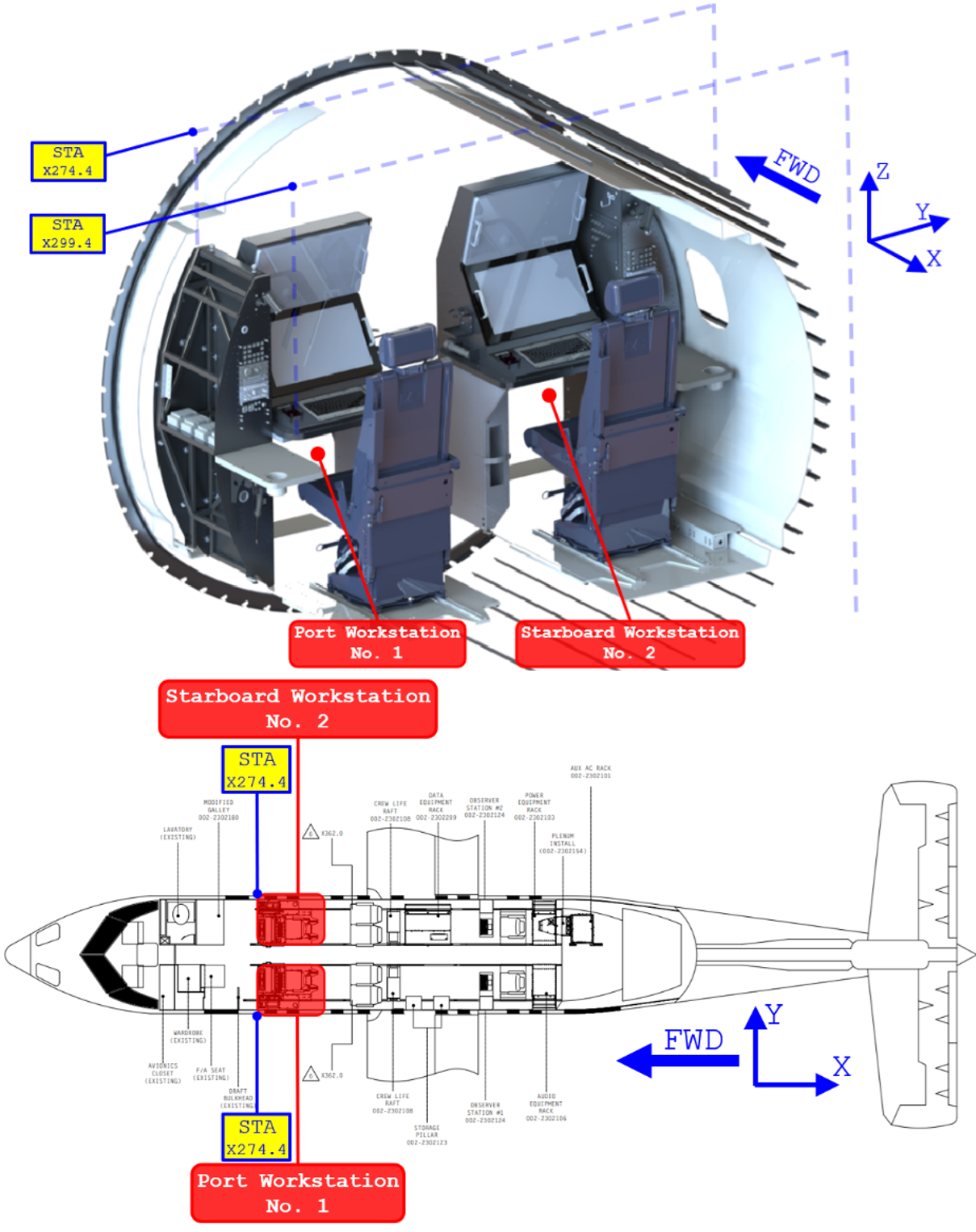
Governing configuration. The Port and Starboard layouts are identical over X274.4–X299.4 and experience the same vertical acceleration environment. Because the Starboard workstation carries the greater equipment mass, it is the governing structural configuration; the Port installation is covered by comparison.
I used the heavier Starboard workstation as the governing configuration and retained the complete structural load path from equipment inertia to the aircraft attachments. Equipment and composite-table masses are introduced through RBE3 elements so their inertia is distributed without artificial stiffness; beam and plate elements then carry the loads through the tube frame, skins, braces, gussets, and attachment fittings. The lower seat-track studs provide the primary translational restraint, while the upper attachments restrain lateral and longitudinal motion but leave vertical translation free. This avoids creating an artificial upper vertical load path while preserving the physical support kinematics.
Mass & CoG Representation
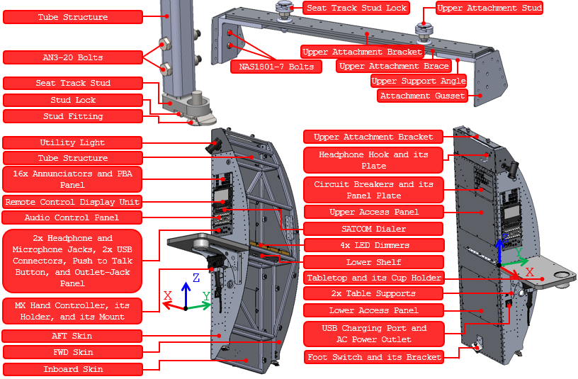
Load-bearing structure remains explicitly modeled. Equipment is introduced at its CoG, while omitted non-load-bearing details are retained as nonstructural mass so the inertia field remains representative without unnecessary geometric detail.
Allowables & Joint Basis
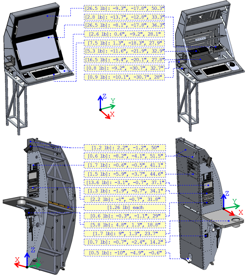
Metallic strength allowables are taken from the cited MMPDS data. Local welded 6061-T6 tube properties are reduced to the applicable weld-zone values rather than using parent-material strength.
Joint capacity is based on the weakest applicable failure path for the actual fastener, insert, sheet and bearing stack—not the isolated fastener catalog strength.
Load Cases Formulation
The installation is screened against the applicable flight and emergency-landing acceleration environment. Vertical flight loads are extracted conservatively at X287.99 within the workstation span, and emergency cases are included where they govern.
Load Cases
Load Case Number |
Load Factor Direction |
Ultimate Load Value () [g] |
Governing basis |
|---|---|---|---|
| 1 | Up | 4.26 | Flight |
| 2 | Down | 6.8 | Flight |
| 3 | Outboard | 3.0 | Emergency landing |
| 4 | Inboard | 3.0 | Emergency landing |
| 5 | Forward | 9.0 | Emergency landing |
| Not required* | Aft | 1.5 | Covered conservatively by Forward case |
| * The Aft case is covered conservatively by the 9g Forward case and is not analyzed separately. | |||
I screened the workstation against the applicable flight and emergency-landing accelerations and retained the governing demand for each direction. The vertical flight cases govern Upward and Downward at 4.26g and 6.80g, while the emergency-landing criteria govern Outboard, Inboard, and Forward at 3g, 3g, and 9g. The 1.5g Aft condition is enveloped by the Forward case, so five distinct ultimate-load cases are sufficient without duplicating a weaker reverse-direction case.
Finite Element Analysis (FEA)
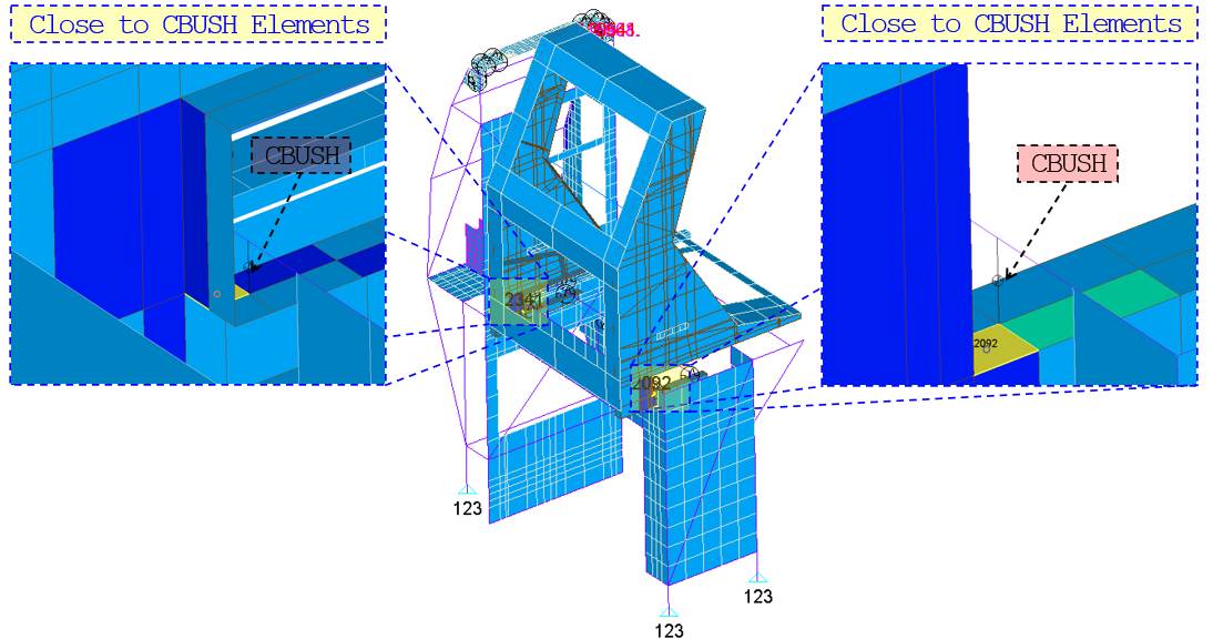
The Starboard workstation is modeled in FEMAP and solved using Simcenter Nastran. The model is intentionally mixed-dimensional: beam elements recover member forces efficiently, plate elements capture membrane/bending response, CBUSH elements provide discrete joint reactions, and RBE3 connections distribute equipment inertia without introducing artificial stiffness.
Model & Idealization
Beam elements · tube & braces
Slender members carry load primarily through axial force, shear and bending. Beam idealization preserves section properties and member force recovery with far lower model cost than solid geometry.
Plate elements · sheet structure
Thin panels and brackets are represented by midsurface plates so membrane and bending stresses are recovered directly through the sheet thickness definition.
CBUSH · discrete fasteners
Node-to-node connector elements preserve a discrete load path and enable direct reaction extraction without rigidly tying the joint rotational behavior.
RBE3 · equipment masses
RBE3 distributes inertia load into surrounding structural nodes without adding artificial stiffness to the supporting panels or tube structure.
NSM · omitted nonstructural content
Panels, hardware and small non-load-bearing items are omitted geometrically but retained as distributed nonstructural mass, preserving inertia while avoiding unnecessary mesh/detail.
Non-penetrating interface
The attachment gusset / upper support angle interface transfers compressive contact load without creating an artificial tensile tie across the mating surfaces.
Upper brace omitted
Removing the brace eliminates a potential parallel load path; the remaining modeled structure therefore carries the reaction without credit for that support contribution.
Noncritical holes covered
Suppressing holes that do not define the primary load path avoids local numerical peaks and reduces mesh density while retaining structural stiffness at the substantiation scale.
Loads & Constraints
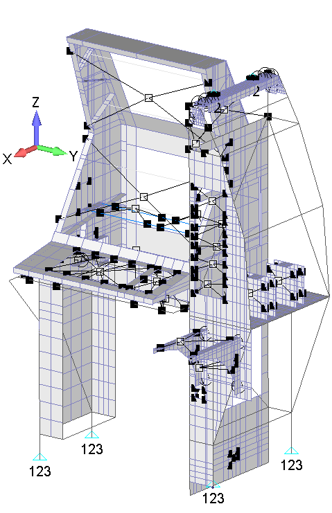
The lower seat-track studs provide the primary translational restraint. Upper attachments restrain lateral and longitudinal motion while leaving vertical translation free, avoiding an artificial vertical load path through the upper support.
Upper attachments: lateral and longitudinal translation restrained; vertical translation remains free.
The constraint set follows the attachment kinematics while avoiding unnecessary upper vertical fixity that would create an artificial load path and over-stiffen the workstation.
Analysis
SESTATIC · SOL 101
Linear static analysis is appropriate for the ultimate inertia load cases used for strength substantiation.
Mass is entered in lbm, density in lbm/in³ and acceleration in in/s². WTMASS provides consistent mass-to-force conversion so solver forces are recovered in lbf and stresses in psi.
Governing Results
The full source analysis evaluates each member, panel, joint and equipment support. For portfolio use, the table below retains the governing or representative checks that best demonstrate the structural substantiation method.
Selected governing structural checks
| Assessment | Demand / basis | Margin | Status |
|---|---|---|---|
| Welded tube · combined axial + bending interaction | Interaction ratios 0.371 + 0.593 | +0.038 | PASS |
| FWD shelf brace · crippling | 23.05 ksi allowable / 22.69 ksi demand | +0.016 | PASS |
| 2024-T3 ALCAD sheet · principal stress | 37 ksi compression basis / 28.30 ksi | +0.31 | PASS |
| 2024-T351 plate · principal stress | 39 ksi compression basis / 28.09 ksi | +0.39 | PASS |
| 6061-T6/T6511 extrusion · principal stress | 34 ksi compression basis / 24.35 ksi | +0.40 | PASS |
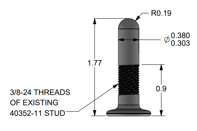
| Upper attachment stud · shear | 481 lbf / (357.70 × 1.15) lbf | +0.17 | PASS |
| Upper seat-track tooth | 2,250 lbf / 1,515.5 lbf | +0.48 | PASS |
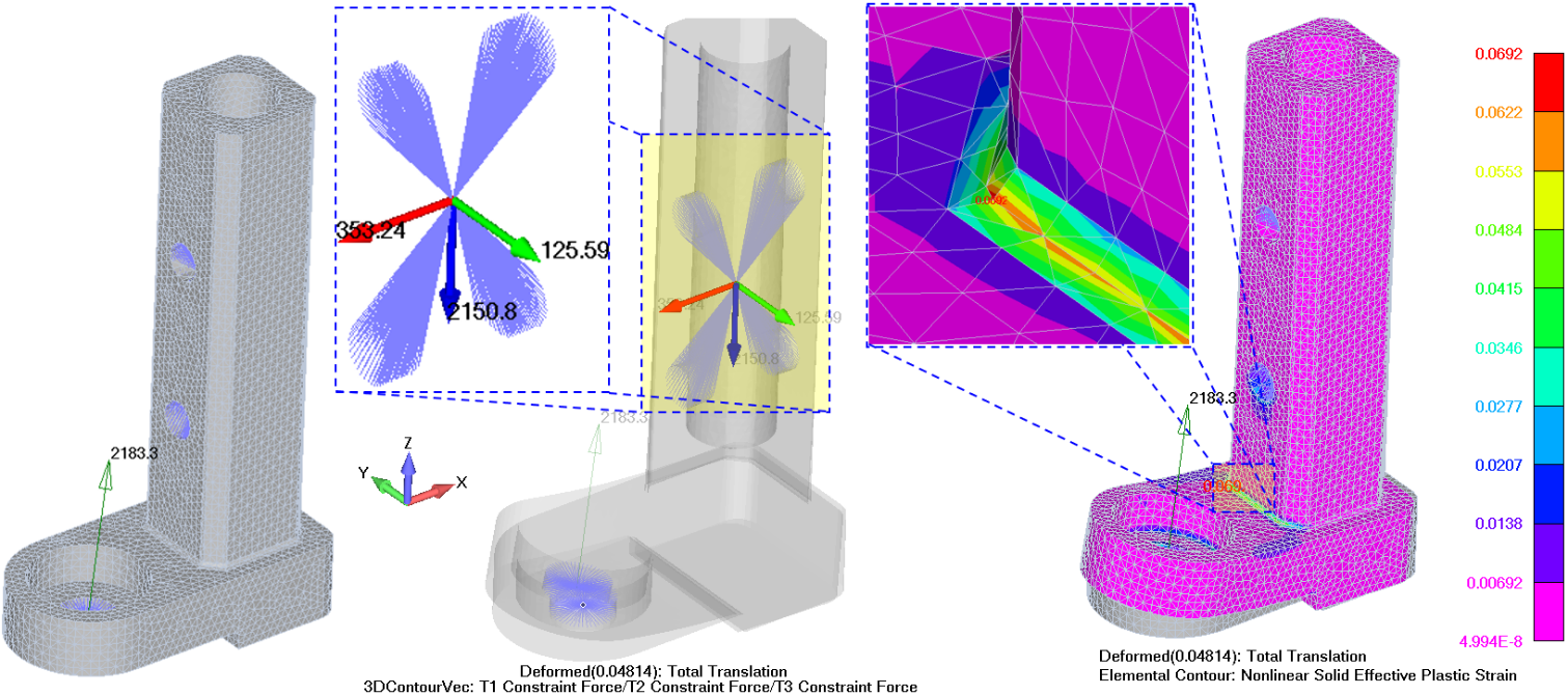
| Seat-track stud · nonlinear check | 0.14 in allowable / 0.0692 in displacement basis | +1.02 | PASS |
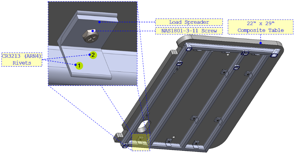
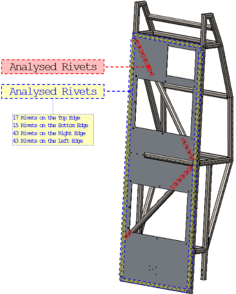
| FWD desk panel · Part 1 rivets | 428 lbf / 401 lbf shear | +0.07 | PASS |
| Inboard tower skin · rivets | 428 lbf / 408.13 lbf shear | +0.05 | PASS |
| Attachment gusset · shear | 482 lbf / 432.71 lbf | +0.11 | PASS |
| Desk-to-tower riveted joint · shear | 316 lbf / (389.93 / 2) lbf | +0.62 | PASS |
Primary Tube Structure
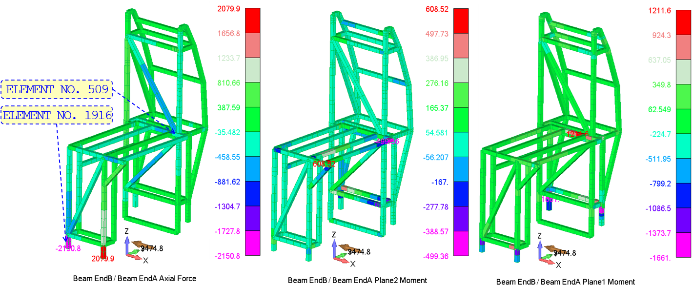
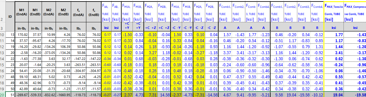
Beam-force recovery is converted to axial and bending stress at the tube extremes, with separate parent-material and weld-zone properties. The combined interaction check at the weld is more critical than simple tension and provides the governing tube-structure margin shown below.
Shelf Braces · Strength & Crippling
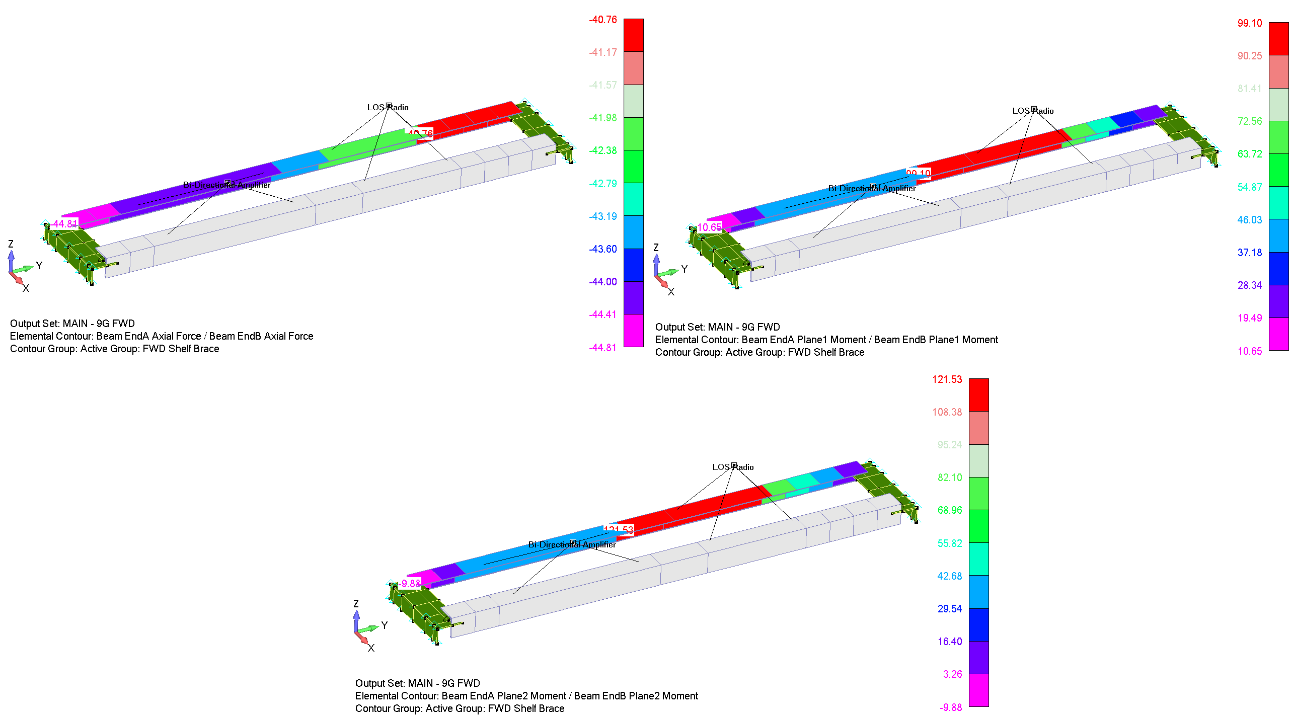
The shelf-brace extrusions are checked for direct tension/compression and local crippling. The forward brace is the critical member, with the crippling allowable only slightly above the maximum compressive demand.
Sheet-Metal Stress Screening
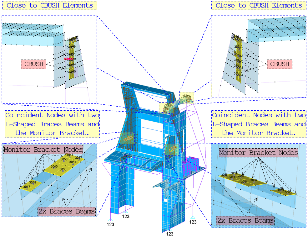
Principal stresses are screened across every load case. Elements outside the source-defined thresholds are flagged for physical review so isolated numerical peaks do not automatically govern without checking their location and structural meaning.
Composite Table Supports
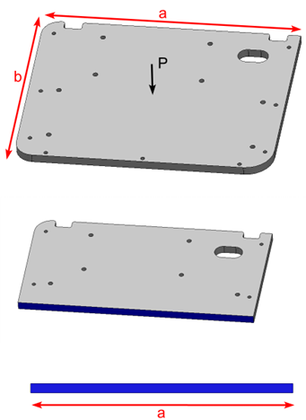
The sandwich tables are checked using conservative simply-supported loading under the 6.8g downward case. For the main table plus mission computer, the calculated core shear stress is 2.95 psi versus published short-beam shear allowables of 262/391 psi; the calculated facing bending stress is 1.071 ksi versus published long-beam facing allowables of approximately 58 ksi. The side table is less critical.
Aircraft Attachment Load Path
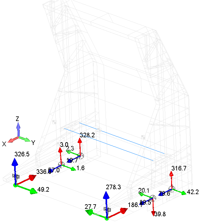
Attachment reactions are extracted directly from the connector model and resolved into tensile/shear demand. The custom upper stud, seat-track tooth and lower seat-track stud are then checked using targeted classical and nonlinear analyses.
Panel Joints & Fastener Load Extraction
Panel membrane resultants, shear flow and transverse shear are converted to discrete edge/fastener loads. The governing panel-joint margins remain positive; representative tight checks include the FWD desk panel rivets (+0.07) and inboard tower-skin rivets (+0.05).
Python-Assisted Plate Post-Processing
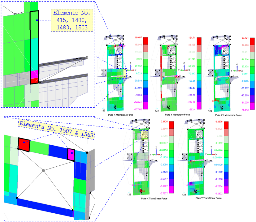
The desk-to-tower attachment demonstrates the workflow used where plate resultants must be converted into discrete fastener demand over many elements and load cases.
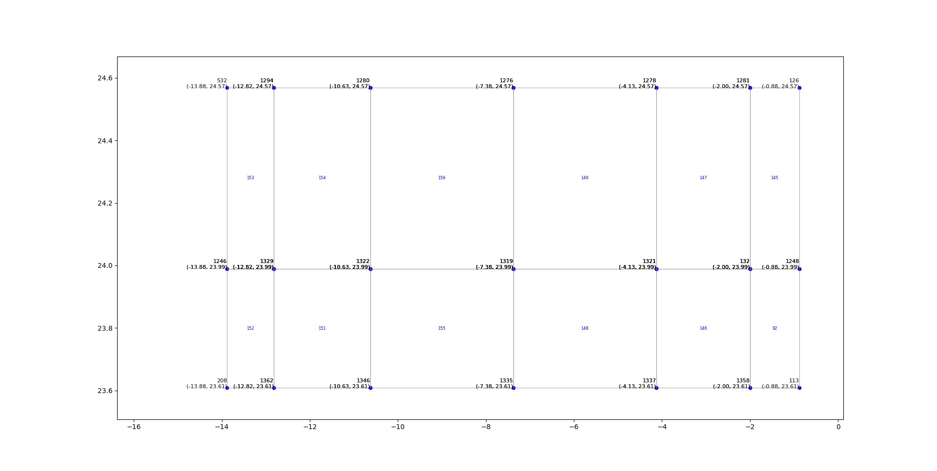
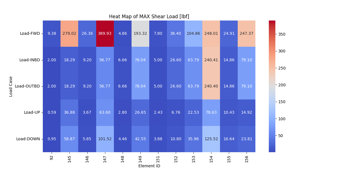
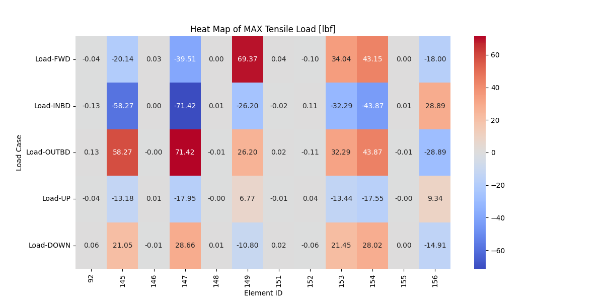
The plate-force post-processing was automated to reduce repetitive manual work and improve traceability. The script reads FEMAP-exported element and nodal data, rejects triangular elements, calculates element dimensions, converts membrane resultants to elemental forces, screens all load cases, and writes governing results to a summary workbook.
- Read the FEMAP Excel export and nodal coordinates.
- Extract nodal-coordinate values (X-Def, Y-Def, Z-Def).
- Filter valid quadrilateral plate elements.
- Calculate element dimensions and local force directions.
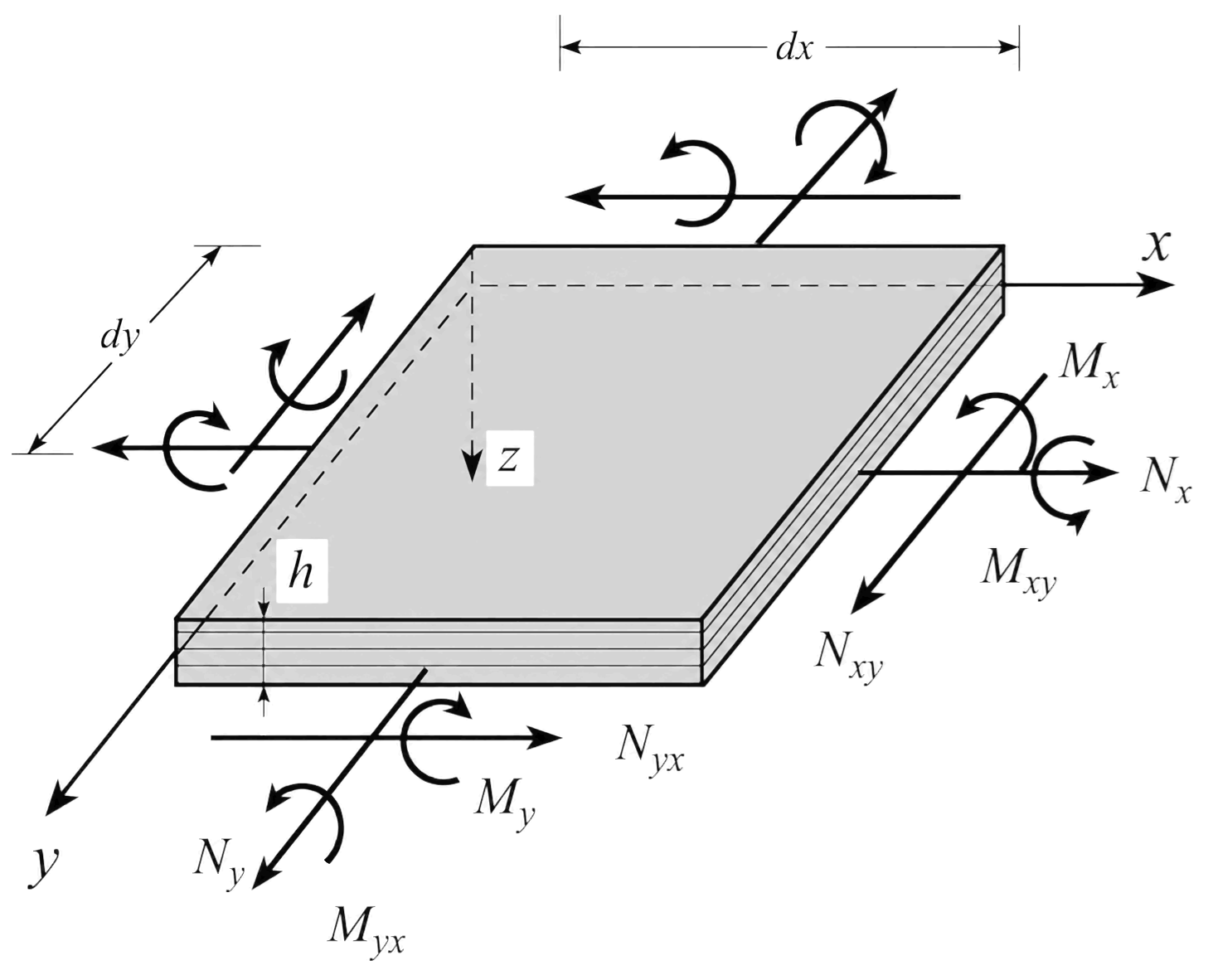
- Recover nx, ny, nxy, qx, and qy for every element and load case.
- Calculate elemental shear and tensile demand.
A conservative in-plane resultant is calculated as:
- Generate contour maps and a governing-result summary.
- 2D plot of elements and nodes.
- Heat maps for maximum shear load and maximum tensile load for every load case.
- Extract maximum membrane forces, shear, and tensile loads from each load case and save them to a new summary table.
Equipment & Secondary Attachments
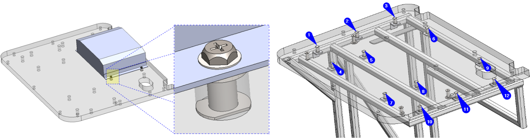
Secondary attachments are screened using extracted CBUSH or nodal reactions against the governing fastener/insert capacity. These checks retain conservative load assumptions while avoiding unnecessary repetition in the portfolio version.
Representative secondary-attachment checks retained from the full analysis
| Installation | Governing extracted demand | Assessment |
|---|---|---|
| Keyboard tray | Part 3 shear = 553.22 lbf → 276.61 lbf per two-screw assumption | NAS8602-2 screws pass by observation |
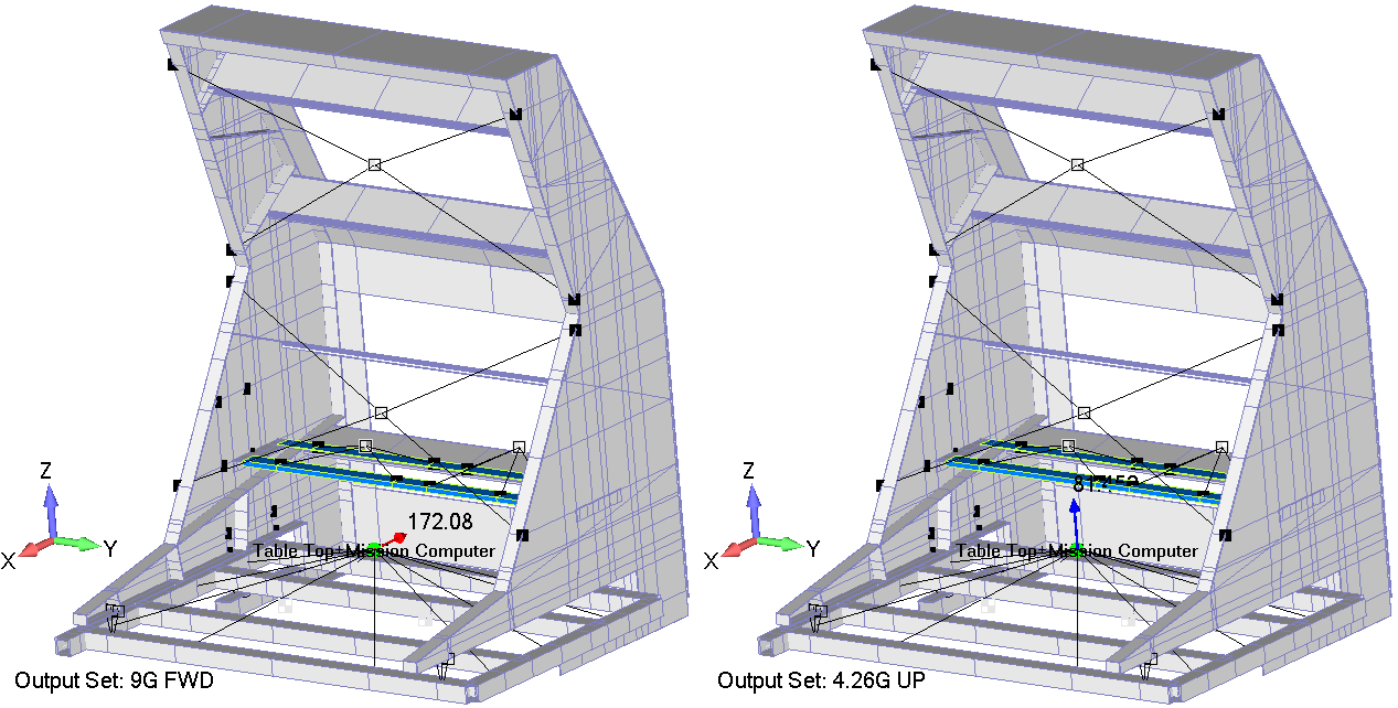
| Mission computer | 172.08 lbf shear; 81.5 lbf tension | NAS1832-3-4 insert governs; pass by observation |
| Monitor bracket | 448.8 lbf shear; 163.26 lbf tension per AN3-15A screw | NAS1834-3-1000 insert governs; pass by observation |
| Monitor close-out | 167.54 lbf max nodal component; conservative combined shear = 201 lbf | NAS8602-2 screws pass by observation |
| Shelf clips | 47.45 lbf max nodal component; conservative combined shear = 61 lbf | MS20426AD4 rivets pass by observation |
| Cross-brace beam attachment | 0.54 lbf maximum extracted load | NAS1801-3-8 screws pass by observation |
References
Structural Methods & Allowables
- MMPDS-15 - Metallic Materials Properties Development and Standardization
- Analysis and Design of Flight Vehicle Structures - E. F. Bruhn
- Aluminum Design Manual 2010
- Stress Analysis Manual - Air Force Flight Dynamics Laboratory, Wright-Patterson
- Fastener Design Manual - NASA Reference Publication 1228
Regulatory & Aircraft Load Basis
- Federal Aviation Regulations - 14 CFR Part 25
- DHC-8-100 Load Cases and Applied Loads
Fasteners & Hardware Data
- CherryMax Rivets technical data
- NAS528 Fastener Codes
- MS24693 technical data
- NAS1832 / NAS1834 insert technical data
- NAS8602 / NAS1801 fastener technical data
Track, Composite & Fitting Data
- ANCRA Aircraft Track technical data
- FE200744 stud technical data
- 40351 / 40352 Threaded Stud specifications
- TEKLAM AA207-66-1000 / AA207-33-1000 technical data