The installation occupies a compact center-fuselage envelope around the X380 analysis station.
INTRODUCTION
Static-strength substantiation of the DHC-8-100 Inertial Navigation and Surveying System (INSGPS) installation. The assessment follows the physical load path from the equipment through the tray, support angles, angle/channel beams and Tee Clips into the existing aircraft structure.
Classical 3D rigid-body equilibrium and beam methods are used to resolve attachment loads, establish joint capacity, and check member strength and local stability against the source material allowables.
AircraftDHC-8-100Exterior structural installation
Installation envelopeX370.8 → X387.35Between stringers 32P and 32S
Conservative payload25.11 lb₍f₎Added structure + equipment, including 15% installation allowance
Substantiation routeClassical + 3D rigid-bodyFasteners, tray, support angles, angle beam and tee clip
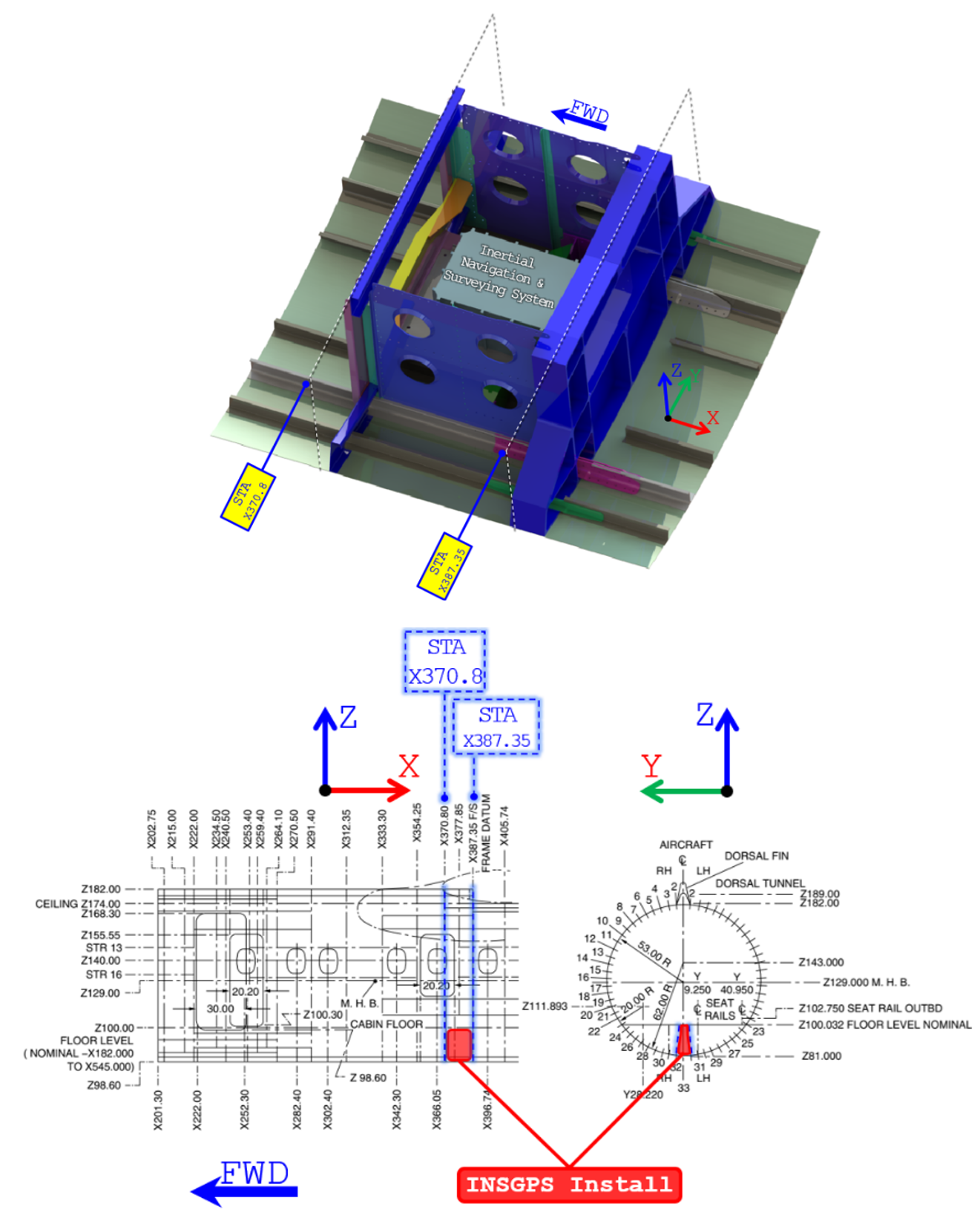
DESIGN ASSESSMENT
Load is introduced into the adjacent keel/floor support structure and stringer attachments.
Tray reactions feed the FWD/AFT supports before entering the angle/channel beam structure.
The final load path is transferred into existing floor/keel structure and the adjacent stringer system.
Load-path driven substantiation
The analysis is organized by successive load-transfer interfaces rather than by part description: equipment bolts → tray bolts → support-angle joints → beam joints → aircraft tie-ins.
I traced the installation as a sequence of discrete interfaces rather than treating it as one equivalent bracket. Equipment inertia is introduced into the tray through the four AN3-7 mounting bolts; the tray transfers the combined payload to the FWD and AFT support angles through AN4-6 bolts. Those reactions then enter the Angle Beam / Channel Beam through Hi-Lok pin-collar joints and finally close into the existing floor-keel and stringer structure through the beam and Tee-Clip attachments. Keeping each interface explicit makes the reaction path auditable and allows the governing fastener, bearing, bending, and local clip checks to be assessed at the physical load-transfer location.
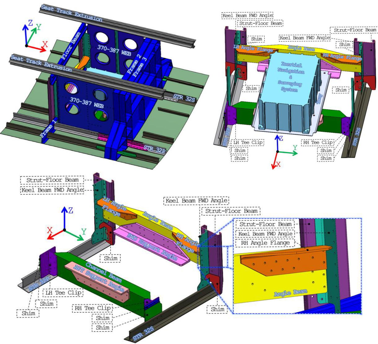
INSGPS Installation Components
The tray receives the equipment inertia through four AN3-7 mounting bolts and transfers the combined load into the support angles through AN4-6 bolts.
FWD/AFT support angles, flange angles, Tee Clips, Angle Beam and Channel Beam provide the principal metallic load-transfer path.
Loads close into the keel/floor support structure and stringers 32P/32S through the beam and Tee-Clip attachments.
Joint checks include fastener shear/tension, local bearing, and conservative single-plane credit where required by the source assessment.
INSGPS Installation Weight Estimation
WEIGHT BUILD-UP
CAD volume × material density
AL 2024-T3 sheet uses 0.100 lbₘ/in³ and AL 6061-T6511 extrusion uses 0.098 lbₘ/in³. Equipment weight is included directly from the source data.
INSTALLATION ALLOWANCE
15% weight growth
Each added component is scaled by 1.15 to account for installation hardware, fasteners and wiring/cabling that are not modeled individually.
REFERENCE AXES
(X,Y,Z) = (AFT, Right, Up)
CoG coordinates are measured from the lower-right corner of the FWD Angle Beam.
Conservative installation mass model retained for structural analysis.
| Quantity | Source value | Engineering use |
|---|---|---|
| Base added system weight | 21.84 lb | CAD/material build-up plus equipment |
| Installation allowance | 15% | Fasteners, wiring/cabling and unmodeled installation items |
| Conservative analysis payload | 25.11 lbf | Applied to the tray and downstream interfaces |
| Weighted CoG | (8.08, −9.12, 1.77) in | Measured from the FWD Angle Beam reference corner |
Weighted-Average CoG
A worked check for the X-coordinate is:
The same procedure produces and .
Conservative analysis payload · 25.11 lb₍f₎
Weighted CoG = (8.08, −9.12, 1.77) in from the FWD Angle Beam reference corner. The complete added-system weight is conservatively treated as payload carried by the tray.
Material Properties
The portfolio summary retains the material values that govern the principal member and joint checks. The full source report contains the complete thickness-dependent MMPDS/MMEAVS table.
Selected structural material allowables used in the retained checks.
| Material / form | Ftu | Fcy | Fsu | Typical use |
|---|---|---|---|---|
| AL 2024-T3 CLAD sheet, 0.063–0.128 in | 62 ksi | 37 ksi | 38 ksi | Tray |
| AL 6061-T6/T6511 extrusion | 38 ksi | 34 ksi | 26 ksi | Support angles / beams / clips |
| AL 7075-T6511 extrusion | 78 ksi | 70 ksi | 41 ksi | Stringer structure |
| AL 7075-T6/T62 sheet, 0.012–0.039 in | 74 ksi | 67 ksi | 47 ksi | Existing sheet structure |
| AL 7075-T73 sheet, 0.040–0.249 in | 67 ksi | 55 ksi | 38 ksi | Existing keel-angle structure |
Fasteners Allowables
Joint allowable philosophy
Size the connection to the weakest applicable failure path for the actual fastener / sheet stack rather than the isolated fastener strength.
Sheet thickness and material can govern the joint.Countersunk geometry is treated with the applicable static-joint reduction.Fastener tension is checked where a meaningful tensile reaction exists.
The usable joint allowable is based on the weakest applicable failure path for the actual fastener/sheet stack rather than on isolated fastener strength.
HL18PB / HL70 · Support-angle joints
Joint stack0.25 in AL 6061-T6511 support angle + 0.1875 in angle/channel beam
Pin shear2,005 lbf
Thin-layer bearing2,402 lbf
Governing shear allowable2,005 lbf
Pin tensile1,940 lbf
Collar tensile / governing tension1,400 lbf
HL18PB / HL70 · Tee Clip to Stringer
Conservative stack0.125 in AL 6061-T6511 Tee Clip + 0.080 in AL 7075-T6511 stringer
Physical jointFour shear planes are present
Credited shear planesOne only - conservative
Pin shear2,005 lbf
Stringer bearing1,750 lbf
Governing shear / tension1,750 / 1,400 lbf
AN4-6A · Tray to Support Angles
Joint stack0.071 in AL 2024-T3 tray + 0.25 in AL 6061-T6511 support
Bolt single shear3,680 lbf
Tray bearing2,218 lbf
Governing shear allowable2,218 lbf
Tensile allowable4,080 lbf
Failure pathTray bearing governs shear-side sizing
AN3-7A · INSGPS Equipment to Tray
Joint stackEquipment flange + 0.071 in AL 2024-T3 tray
Bolt single shear2,125 lbf
Tray bearing1,686 lbf
Governing shear allowable1,686 lbf
Tensile allowable2,210 lbf
Failure pathTray bearing governs shear-side sizing
LOAD CASES FORMULATION
REGULATORY SOURCE BASISFAR criteria used to establish the applicable structural load environment
Flight loads · FAR 25.321 and 25.331–25.351
- General flight-load requirements
- Maneuver and flight-envelope conditions
- Design airspeeds and maneuver load factors
- Gust/turbulence, high-lift, rolling and yaw conditions
Emergency landing context · FAR 25.561
- Forward: 9 g
- Downward: 6 g
- Upward: 3 g
- Sideward: 3 g on airframe; 4 g on seats/attachments
- Rearward: 1.5 g
The installation spans X370.8–X387.35. The source analysis uses X380.00 as a conservative station and retains the governing flight acceleration in each direction. A 1.5 factor is carried explicitly from limit to ultimate demand.
LIMIT → ULTIMATE
Ultimate factor retained explicitly
The source uses a 1.5 factor between limit and ultimate demand.
Governing limit-load cases used for structural substantiation.
Load Case Number |
Load Factor Direction |
The Governing Limit Load Case (g) |
Governing basis |
|---|---|---|---|
| 1 | Upward | 3.72 | Flight |
| 2 | Downward | 5.1 | Flight |
| 3 | Outboard | 0.96 | Flight |
| 4 | Inboard | 0.97 | Flight |
| 5 | Forward | 0.57 | Flight |
| Not required* | Aft | 0.11 | Covered conservatively by Forward case |
| *This case is covered by the Forward case, so it will not be required | |||
The installation is treated as an exterior aircraft modification, so the substantiation is driven by the governing flight accelerations rather than cabin emergency-landing factors. I selected the conservative X380 station within the installation envelope and retained the worst limit acceleration in each direction: 3.72g Upward, 5.10g Downward, 0.96g Outboard, 0.97g Inboard, and 0.57g Forward. The 0.11g Aft case is enveloped by the Forward case and is therefore not modeled separately. This keeps the load set complete, traceable, and free of a redundant weaker reverse-direction case.
CLASSICAL ANALYSIS
Resolve four AN3-7 bolt reactions with 3D rigid-body equilibrium.
Resolve AN4-6 reactions and idealize tray response in principal L/LT directions.
Use simply supported beam models with conservative peak bolt loads.
Carry demand through the Angle Beam and Tee Clip into the existing structure.
Common conservative payload basis
The complete 25.11 lb₍f₎ added-system weight is treated as tray payload at the weighted CoG so each downstream interface is checked against an intentionally conservative common load basis.
Governing retained structural results.
| Assessment | Governing demand / method | Result | Status |
|---|---|---|---|
| Tray Beam A · tension | 36.53 ksi limit stress; 1.5 ultimate factor | MS = +0.13 | PASS |
| Tray Beam A · compression/bending interaction | Cozzone / modulus-of-rupture treatment | MS = +0.547 | PASS |
| FWD Support Angle | 0.94 ksi tension / −0.73 ksi compression | Below 6061-T6511 allowables | PASS |
| Angle Beam · combined stress | 19.92 ksi tension / −13.87 ksi compression | MS = +0.27 / +0.63 | PASS |
| Angle Beam · flange crippling | 15.36 ksi applied vs 31.06 ksi crippling | MS = +0.35 | PASS |
| Tee Clip | Top: 280.09 psi shear / 945.11 psi normal | Below 6061-T6511 allowables | PASS |
Minimum retained margin: +0.13
The tray longitudinal Beam A tensile check is the tightest explicit margin retained in this portfolio summary. All retained member and joint checks remain positive or pass by the source observation criteria.
Inertial Navigation and Surveying Equipment
MOUNTING
4 × AN3-7 bolts
Equipment CoG = (8.98, −9.12, 2.65) in. The full 25.11 lb₍f₎ conservative payload is used for attachment screening.
LOAD EXTRACTION
3D rigid-body equilibrium
For each flight direction, the solver resolves bolt-group shear, compression/tension and the moment about the fastener-group centroid.
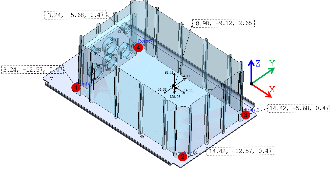
Maximum shear and axial demand at one INSGPS equipment mounting bolt .
Shear (lbf) |
Axial | ||
|---|---|---|---|
Compression (lbf) |
Tensile (lbf) |
||
| 0.57g Forward Case | 3.58 | 1.66 | 1.66 |
| 0.97g Inboard Case | 6.21 | 4.60 | 4.60 |
| 0.96g Outboard Case | 6.15 | 4.55 | 4.55 |
| 3.72g Upward Case | 0.00 | 0.00 | 24.03 |
| 5.1g Downward Case | 0.00 | 32.94 | 0.00 |
| MAXIMUM | 6.21 | 32.94 | 24.03 |
Engineering readout. The governing per-bolt demand is 6.21 lbf shear, 32.94 lbf compression and 24.03 lbf tension. The AN3-7A joint allowable retained from the source is 1,686 lbf in shear and 2,210 lbf in tension, so the equipment attachment is non-governing. The resolved bolt-group moments are carried forward into the tray assessment.
Resultant moment about the INSGPS equipment fastener-group centroid for each load case.
Mx (in-lbf) |
My (in-lbf) |
Mz (in-lbf) |
|
|---|---|---|---|
| 0.57g Forward Case | 0.00 | -31.13 | 0.07 |
| 0.97g Inboard Case | 52.98 | 0.00 | -3.73 |
| 0.96g Outboard Case | -52.43 | 0.00 | 3.69 |
| 3.72g Upward Case | 0.47 | -14.31 | 0.00 |
| 5.1g Downward Case | -0.64 | 19.63 | 0.00 |
INSGPS Tray
Four AN4-6 bolts transfer the conservative 25.11 lbf payload into the FWD and AFT supports. The governing resolved tray-bolt values are 8.06 lbf shear and 47.78 lbf axial demand in the source reaction table.
Tray-attachment bolt resultant shear and axial demand.
| Bolt #1 | Bolt #2 | Bolt #3 | Bolt #4 | |||||
|---|---|---|---|---|---|---|---|---|
| Shear Load | Axial Load | Shear Load | Axial Load | Shear Load | Axial Load | Shear Load | Axial Load | |
| (lbf) | (lbf) | (lbf) | (lbf) | |||||
| 0.57g FORWARD CASE | 3.58 | 1.30 | 3.58 | 1.30 | 3.58 | -1.30 | 3.58 | -1.30 |
| 0.97g INBOARD CASE | 4.49 | 2.79 | 4.49 | -2.79 | 8.06 | 2.79 | 8.06 | -2.79 |
| 0.96g OUTBOARD CASE | 4.44 | -2.76 | 4.44 | 2.76 | 7.98 | -2.76 | 7.98 | 2.76 |
| 3.72g UPWARD CASE | -11.85 | -11.92 | -34.79 | -34.85 | ||||
| 5.1g DOWNWARD CASE | 16.25 | 16.34 | 47.69 | 47.78 | ||||
| MAX SHEAR | 8.06 | |||||||
| MAX TENSILE | 47.78 | |||||||
| MAX COMPRESSIVE | -34.85 | |||||||
I decomposed the tray into two orthogonal beam strips because the source reactions and moments naturally separate into the tray’s longitudinal (L) and transverse (LT) directions. Beam A receives the longitudinal force system and bending about the transverse axis; Beam B receives the lateral force system and the complementary bending component. Loads omitted from one strip are explicitly carried by the other, while torsional components are conservatively assigned to the adjacent structural load path. This keeps the hand calculation transparent without double-counting reaction components.
Longitudinal tray response
Fastener reactions at the FWD and AFT ends are grouped to capture axial force and bending in the tray’s principal longitudinal direction.
Transverse tray response
Port and starboard fastener reactions are grouped to capture transverse axial/bending response independently.
Assign each reaction to the governing plane
Longitudinal reactions are carried by Beam A and lateral reactions by Beam B; corresponding x/y bending moments are assigned to the beam that represents that plane.
Adjacent structure carries secondary torsion
The source idealization neglects the non-governing torsional component in the orthogonal beam model to keep the hand analysis tractable while preserving the primary bending/axial load paths.
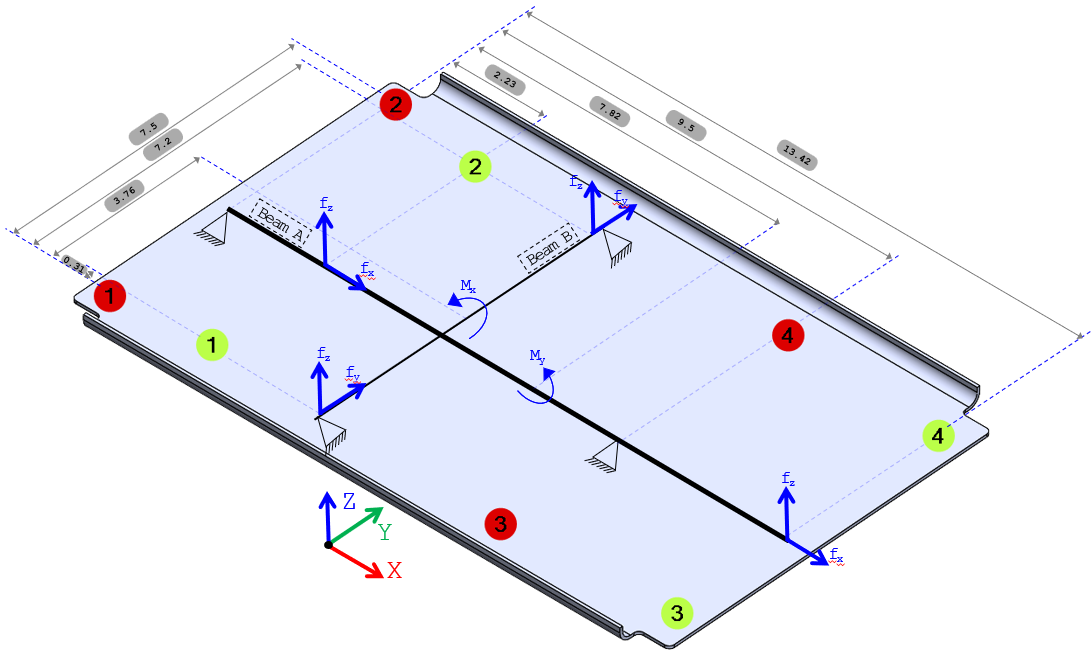
Condensed governing tray-beam response used for the hand checks.
| Idealized member | Peak axial | Peak shear | Governing bending moments |
|---|---|---|---|
| Beam A · longitudinal | 7.16 lbf | 65.80 lbf | My = +188.082 / −257.9 in-lbf; Mz = ±3.73 in-lbf |
| Beam B · transverse | 12.18 lbf | 64.11 lbf | Mx = ±26.52 in-lbf; Mz = ±3.73 in-lbf |
Beam A is governing. Elastic bending gives a maximum 36.53 ksi tensile stress. Because the source notes that this enters the plastic range, the retained assessment uses the Cozzone plastic-bending method and the cross-section shape factor to establish a bending modulus of rupture.
→ PASS
→ PASS
Beam B produces much smaller axial and bending stresses and passes by observation in the source analysis.
FWD Support Angle
LOAD SOURCEPeak AN4-6 tray-bolt reactions
IDEALIZATIONL-section simply supported beam · two point loads
DOWNSTREAM JOINT14 × HL18PB/HL70 pin-collar fasteners
The support is conservatively loaded with peak tray-bolt components combined as if simultaneous, intentionally overbounding the member and its downstream Hi-Lok joint.
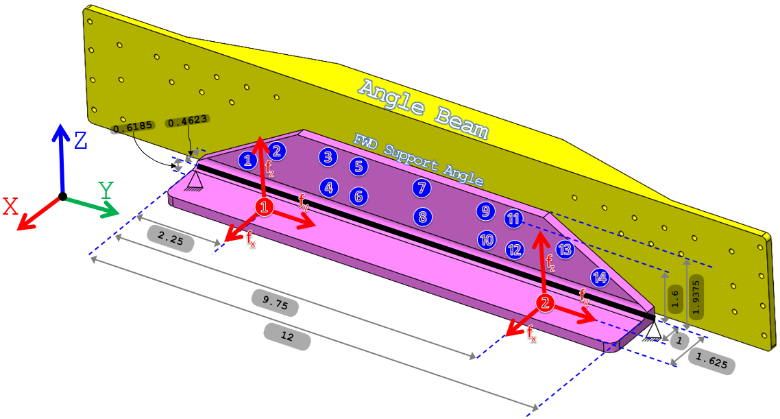
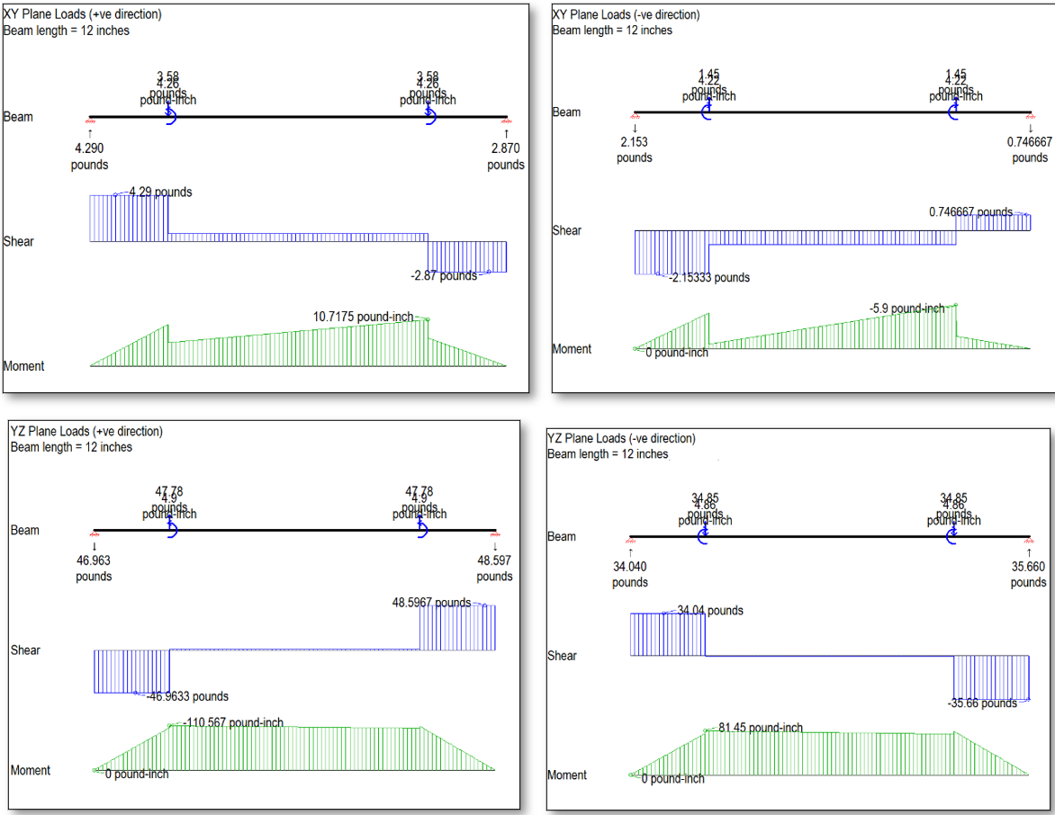
FWD Support Angle governing reactions, axial load and bending moments.
| Direction | + | - | Unit | |
|---|---|---|---|---|
| Rx Reaction Force | End A | 4.29 | 2.15 | lbf |
| End B | 2.87 | 0.75 | lbf | |
| Ry Reaction Force | End A | 7.85 | 7.93 | lbf |
| End B | 7.85 | 7.93 | lbf | |
| Rz Reaction Force | End A | 34.04 | 46.96 | lbf |
| End B | 35.66 | 48.60 | lbf | |
| Beam Axial Force | - | 7.93x2=15.86 | 7.85x2=15.7 | lbf |
| Mx Bending Moment | - | 81.45 | 110.57 | lbf-in |
| Mz Bending Moment | - | 10.72 | 5.9 | lbf-in |
The retained beam check gives maximum combined stresses of 0.94 ksi tension and −0.73 ksi compression, well below the AL 6061-T6511 strength basis.
The same source model also checks local tension-clip action by converting the flange eccentricity into additional fastener tension:
The source compares 154.96 lbf at the AN4-6 side and 32.62 lbf at the HL18PB/HL70 side against 4,080 lbf and 1,400 lbf tensile allowables, respectively; both pass.
AFT Support Angle
LOAD SOURCEPeak AN4-6 tray-bolt reactions
IDEALIZATIONL-section simply supported beam · two point loads
DOWNSTREAM JOINT14 × HL18PB/HL70 pin-collar fasteners
The AFT member uses the same conservative peak tray-bolt envelope, with geometry-specific eccentricity and reactions.
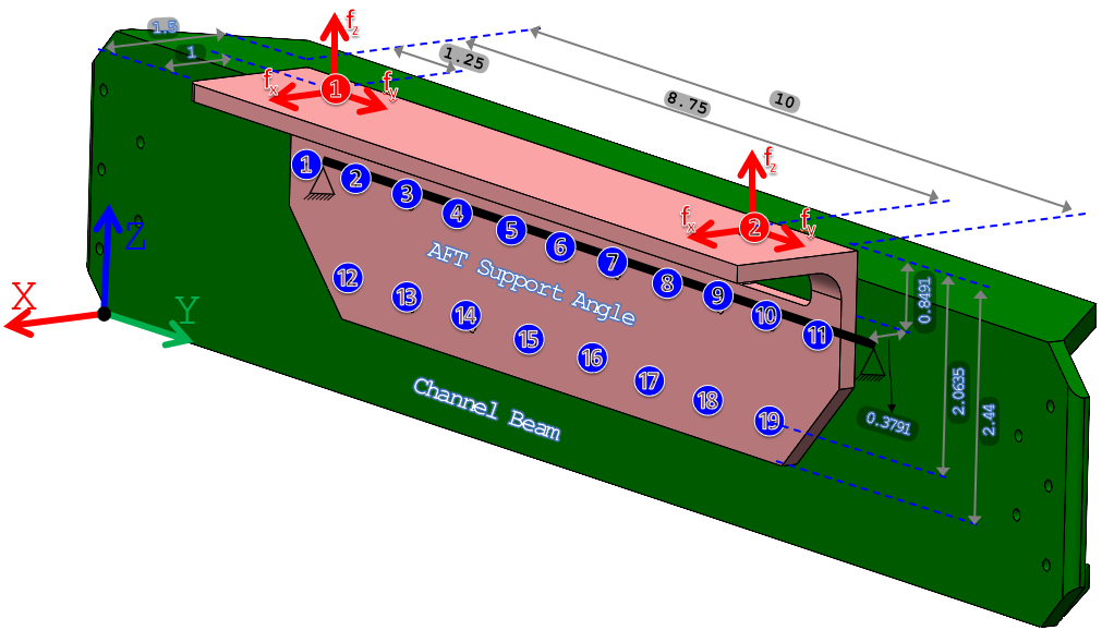
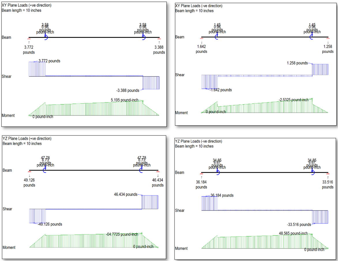
AFT Support Angle governing reactions, axial load and bending moments.
| Direction | + | - | Unit | |
|---|---|---|---|---|
| Rx Reaction Force | End A | 3.77 | 1.64 | lbf |
| End B | 3.39 | 1.26 | lbf | |
| Ry Reaction Force | End A | 7.85 | 7.93 | lbf |
| End B | 7.85 | 7.93 | lbf | |
| Rz Reaction Force | End A | 36.18 | 49.13 | lbf |
| End B | 33.52 | 46.43 | lbf | |
| Beam Axial Force | - | 7.93x2=15.86 | 7.85x2=15.7 | lbf |
| Mx Bending Moment | - | 48.57 | 64.77 | lbf-in |
| Mz Bending Moment | - | 5.2 | 2.53 | lbf-in |
The source checks 210.23 lbf at the AN4-6 side and 32.62 lbf at the HL18PB/HL70 side against the same 4,080 lbf and 1,400 lbf tensile allowables; both pass.
Angle Beam
LOAD SOURCEFWD Support Angle joint reactions
IDEALIZATIONL-section simply supported beam · distributed joint load
DOWNSTREAM JOINT14 × HL40/HL70 pin-collar fasteners
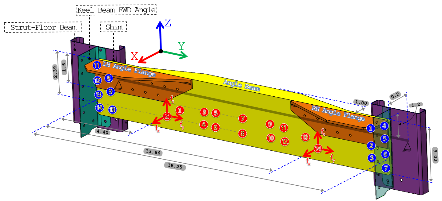
Loads from the FWD support-angle joint are represented as distributed load along the Angle Beam. Peak components from separate cases are conservatively enveloped before the downstream joint and member checks.
Angle Beam idealized distributed loads and applied moments.
| Plane | XY | YZ | ||
|---|---|---|---|---|
| Direction | + | - | + | - |
| Distributed load | 2.9/9.46=0.31 | 32.62/9.46=3.45 | 69.7/9.46=7.37 | 95.56/9.46=10.10 |
| Bending Moment | 3.14 | 3.17 | 12.48 | 12.61 |
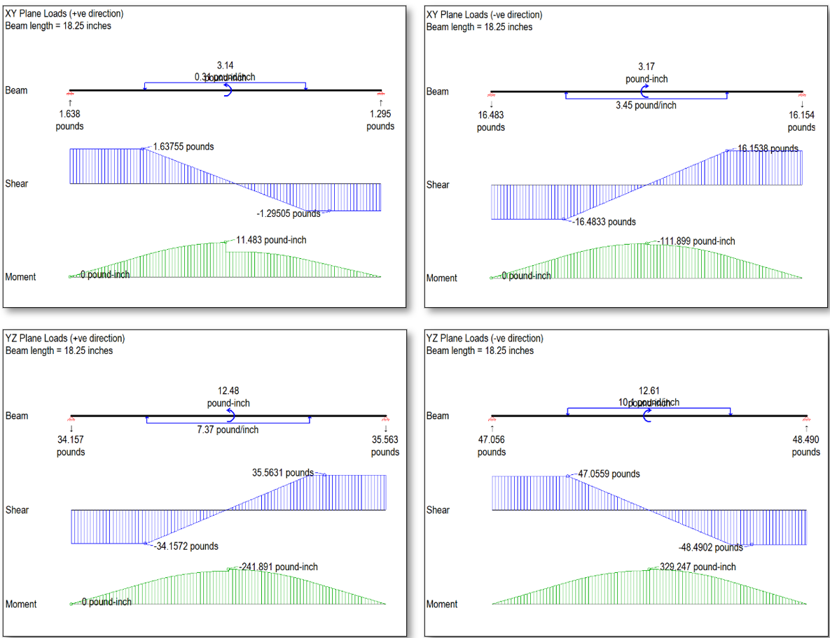
Angle Beam governing reactions, axial load and bending moments.
| Direction | + | - | Unit | |
|---|---|---|---|---|
| Rx Reaction Force | End A | 1.64 | 16.48 | lbf |
| End B | 1.30 | 16.16 | lbf | |
| Ry Reaction Force | End A | 15.86/2=7.93 | 15.7/2=7.85 | lbf |
| End B | 15.86/2=7.93 | 15.7/2=7.85 | lbf | |
| Rz Reaction Force | End A | 47.06 | 34.16 | lbf |
| End B | 48.50 | 35.56 | lbf | |
| Beam Axial Force | - | 15.7 | 15.86 | lbf |
| Mx Bending Moment | - | 329.25 | 241.90 | lbf-in |
| Mz Bending Moment | - | 11.48 | 111.90 | lbf-in |
The 14 × HL40/HL70 connection is also checked for local tension-clip action. The resulting source tensile demand is:
19.33 lbf is small relative to the 1,350 lbf source tensile capacity of the HL40 pin in this configuration.
Combined member stress is checked against AL 6061-T6511 tension/compression allowables:
→ PASS
Local flange stability is retained because it is a distinct failure mode. The source computes a 31.06 ksi crippling stress and compares it with the governing 15.36 ksi compressive demand:
→ PASS
Tee Clip
The final interface distributes the Channel Beam reactions into the Tee Clip and adjacent stringer attachment. The source deliberately ignores several available fasteners when distributing load, providing a conservative joint screen.
The previous analysis of the Channel Beam has shown that the maximum reaction forces carried by the all 5x18PB/HL70 (YA5) Pin-Collar Fasteners are:
Along the positive direction: fx=32.61 lb₍f₎f, fy=15.86 lb₍f₎f, and fz=95.58 lb₍f₎f.
Along the negative direction: fx=2.91 lb₍f₎f, fy=15.70 lb₍f₎f, and fz=69.71 lb₍f₎f.
For conservatism, it is assumed that:
The loads belong to the same loading case, while these loads came from different loading cases.
Fasteners No. 3, 4, and 5 at the top of the tee clip are ignored.
Fasteners No. 1 and 3 at the leg of the tee clip are ignored.
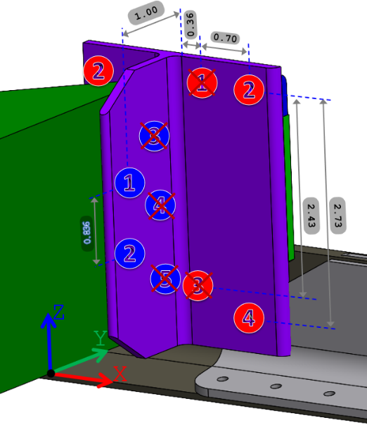
Conservative Tee-Clip fastener demand retained from the source load distribution.
| Location | Resultant fastener shear | Key local stresses |
|---|---|---|
| Top fasteners #1/#2 | 168.19 lbf | 280.09 psi shear; 945.11 psi normal |
| Leg fasteners #2/#4 | 60.07 lbf | 140.07 psi shear; 322.99 psi normal |
Tee Clip · Top
Maximum shear load on the top: = 47.79 × 2 = 95.58 lbf.
Maximum normal load on the top: = 161.26 × 2 = 322.52 lbf.
Tee Clip · Leg
Maximum shear load on the leg: = 23.90 × 2 = 47.8 lbf.
Maximum normal load on the leg: = 55.11 × 2 = 110.22 lbf.
The tee clip is made from 0.125” thick AL 6061-T6511 Extrusion which has an Ultimate Shear Strength value of Fsu=26 ksi, and a Yield Compressive Strength value of Fcy=34 ksi (referencing the corresponding table). Therefore, the tee clip pass by observation.
REFERENCES
Structural Methods & Allowables
- MMPDS-15 - Metallic Materials Properties Development and Standardization
- MMEAVS-2003 - metallic material-property basis used in the source report
Regulatory & Aircraft Load Basis
- Federal Aviation Regulations - 14 CFR Part 25
- DHC-8-100 Load Cases and Applied Loads
Fasteners & Hardware Data
- Standards Committee for Hi-Lok Products - HL18, HL40 and HL70
- NASM3-20 aircraft-bolt technical data
Classical Stress Analysis Methods
- Analysis and Design of Flight Vehicle Structures - E. F. Bruhn
- Analysis & Design of Composite & Metallic Flight Vehicle Structures - Richard Abbott
- Roark’s Formulas for Stress and Strain - 9th Edition