Analysis Overview
The forward side skin panel is substantiated for the maximum upper-compartment demand in the forward 9g condition. The local model combines the sheet panel and surrounding tube frames, then checks the panel using both linear-elastic and nonlinear material response before addressing the rivet pull-out demand separately.
Thin sheet as plates; surrounding tubes as beams
The skin is represented with plate elements to resolve membrane and bending stress over the sheet, while the slender closed-section frame members are represented efficiently with beam elements using their 1 × 1 × 0.125 in hollow-square section.
This preserves the dominant stiffness and load-transfer mechanisms without introducing unnecessary 3D-solid detail into a local static model.
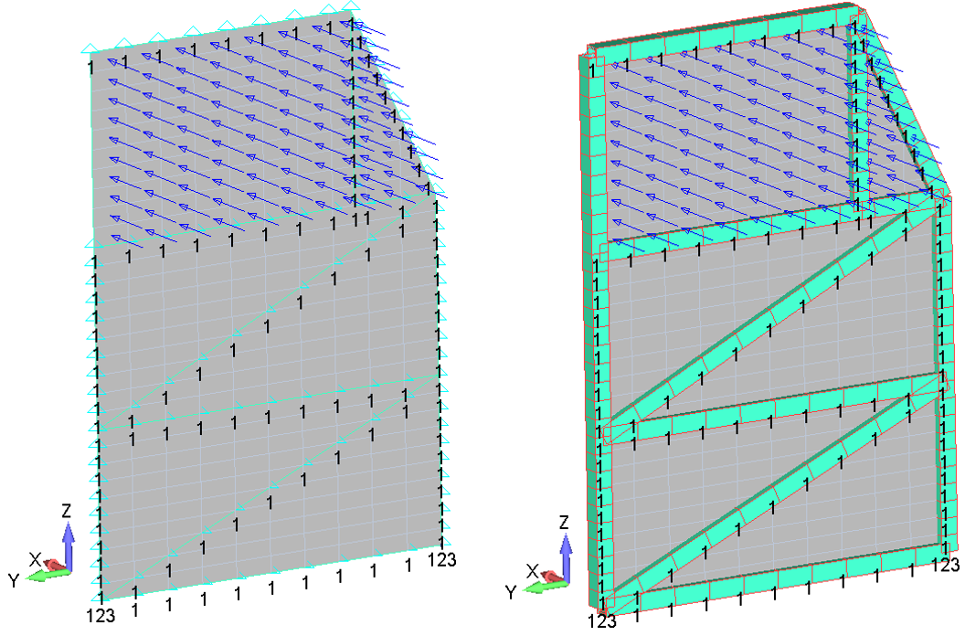
I retained the surrounding tube frames in the local FEM to represent the stiffness that supports the skin panel, and I merged the common plate/beam nodes so load can pass directly between both idealizations. For demand, however, I credited no frame sharing: the complete forward-case compartment load is applied to the skin panel. This separates realistic boundary stiffness from a deliberately conservative panel demand and keeps the local model efficient and auditable.
- Tx: restrained on tube frames except at the compartment opening.
- Ty and Tz: restrained at the bottom of the local model.
The restraint pattern suppresses rigid-body motion while allowing the opening region to deform locally. Because local restraints can amplify nearby stress, those peaks are treated conservatively rather than filtered out.
Load Application
The two upper compartments are rated at 40 lbf each. The complete 80 lbf compartment demand is multiplied by the forward 9g load factor and, conservatively, assigned entirely to the skin panel rather than sharing load with the surrounding tube structure.
The forward-case resultant is:
The loaded upper-panel area is 206.56 in2. The equivalent uniform pressure applied normal to the plate in the positive x-direction is:
Governing load condition used for the local panel assessment.
| Case | Direction | Payload [lbf] | Load factor [g] | Applied load [lbf] | Governing basis |
|---|---|---|---|---|---|
| 1 | Forward | 80 | 9.0 | 720 | Maximum total upper-compartment demand identified in the source assessment |
This standalone assessment is intentionally scoped to the forward 9g condition identified in the source as the maximum total upper-compartment load case. The two 40 lbf compartment capacities are combined, and the full 720 lbf resultant is applied to the panel. No additional load cases are introduced because they are not part of this source section.
Crediting none of the surrounding frame capacity in distributing the 720 lbf demand forces the full compartment load through the panel idealization. This deliberately biases the panel stress assessment on the conservative side.
Linear Static Analysis
- SIMCENTER NASTRAN
- SOL 101 linear static solution
- Static pressure loading
- Plate + beam local model
Principal-stress comparison
The source methodology compares the maximum tensile principal stress against Ftu and the maximum compressive principal stress against Fcy, using both plate surfaces.
Keeping top- and bottom-surface principal stresses visible is important for a thin plate because local bending can reverse the sign and magnitude of stress through the sheet thickness.
Linear-analysis principal-stress envelope. The highlighted cells represent the governing tensile and compressive principal stresses.
| AL 2024-T3 CLAD Sheet | Forward Case | Maximum Tension [ksi] | Maximum Compression [ksi] | ||
|---|---|---|---|---|---|
| Surface | Response | F1 [ksi] | F2 [ksi] | ||
| Top | Tension | 23.33 | 13.58 | 33.50 | −33.50 |
| Compression | −10.70 | −33.50 | |||
| Bottom | Tension | 33.50 | 10.70 | ||
| Compression | −13.58 | −23.33 | |||
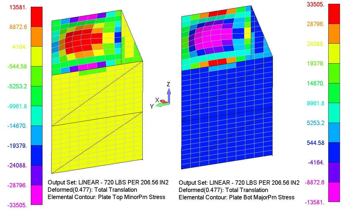
Observed behavior: the governing principal-stress peaks occur at elements connected to restrained nodes, where local boundary conditions can produce irregular stress concentrations.
Assessment decision: rather than filtering or excluding those peaks, the source deliberately retains them in both the linear and nonlinear strength checks. This is conservative because the reported margins are based on the local restrained-node maxima, not a smoothed or de-peaked field.
The material allowables used are Ftu = 62 ksi and Fcy = 37 ksi.
Nonlinear Material Analysis
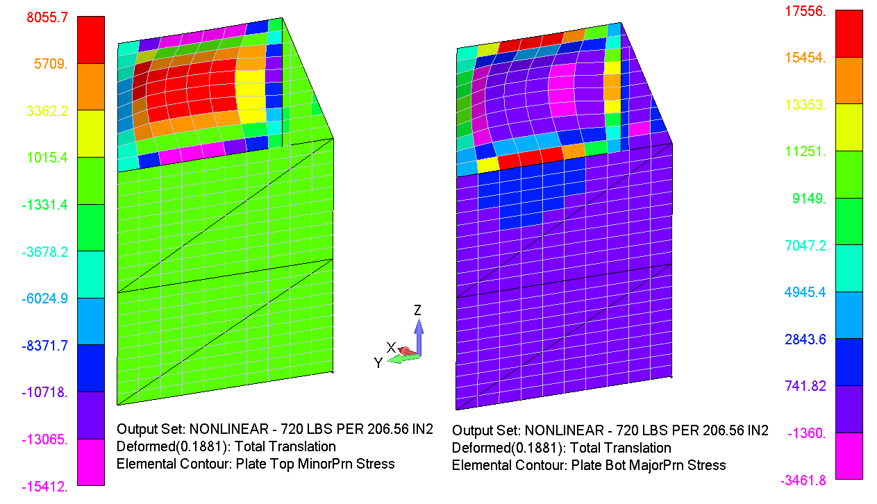
The same local model and loading are retained, but the material response is changed to a nonlinear plastic formulation in SOL 106. The stress–strain relation is represented with discrete points extracted from the source material curves for the panel and tube-frame alloys.
Capture post-yield stress redistribution
A purely linear-elastic solution continues increasing stress in direct proportion to load. The nonlinear material model permits stiffness change after yielding and redistributes local demand while maintaining the same geometry, restraints, and applied pressure.
Because the boundary conditions and loading are unchanged, the nonlinear solution provides a direct comparison of material-model influence rather than mixing changes in load path or restraint.
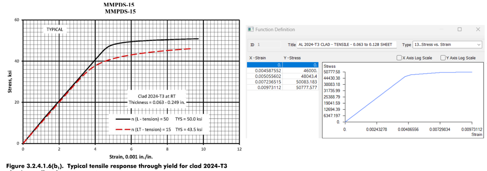
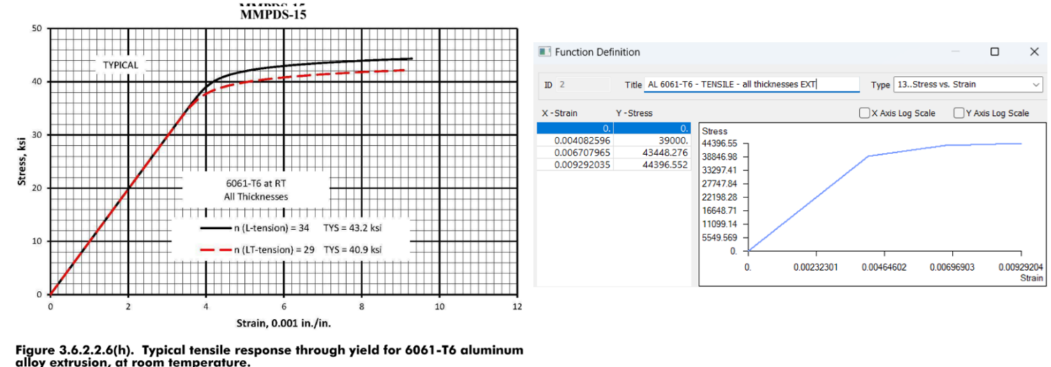
Nonlinear-analysis principal-stress envelope. The highlighted cells represent the governing tensile and compressive principal stresses.
| AL 2024-T3 CLAD Sheet | Forward Case | Maximum Tension [ksi] | Maximum Compression [ksi] | ||
|---|---|---|---|---|---|
| Surface | Response | F1 [ksi] | F2 [ksi] | ||
| Top | Tension | 9.59 | 8.06 | 17.56 | −15.41 |
| Compression | −6.33 | −15.41 | |||
| Bottom | Tension | 17.56 | 5.45 | ||
| Compression | −3.46 | −10.25 | |||
Fastener Assessment
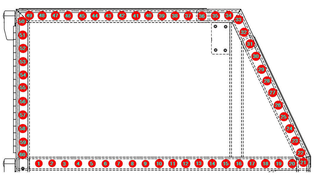
Sixty CR3212 (ARM4) rivets attach the upper-compartment panel region to the tube structure. The local FEM does not include the complete adjacent load path needed to resolve rivet shear accurately, so the fastener check is intentionally separated from the panel stress model.
Rivet shear is not extracted from the local panel FEM
The panel model fixes the surrounding frame longitudinally and omits adjacent structure, so it cannot reproduce the complete shear load path through the riveted joint.
The full 720 lbf forward-case load is treated as panel pull-out and only ten rivets are credited with sharing it equally.
Demand per credited rivet:
- Material: AL 5056 alloy
- Reference tensile strength: 285 lbf for a 0.156 in countersunk sheet
- Panel sheet thickness: 0.0625 in
- Source method scales the tensile capacity with sheet thickness
Scaled tensile capacity for the actual panel thickness:
The source margin calculation applies an additional 1.15 multiplier to the rivet demand term:
Substantiation Outcome
All evaluated static-strength checks pass.
- The panel passes the linear principal-stress assessment even when restrained-node hot spots are retained.
- The nonlinear material solution shows substantial redistribution of the local stress peaks while preserving positive margin.
- The CR3212 rivets pass the separate conservative tensile pull-out check used because the local FEM does not resolve the complete joint shear load path.
References
Material Allowables & Constitutive Data
- MMPDS-15 — Metallic Materials Properties Development and Standardization
Analysis Solver & Methods
- SIMCENTER NASTRAN — SOL 101 linear static and SOL 106 nonlinear static analysis