Analysis Overview
Local FEM substantiation of the forward side skin panel for the governing forward 9g compartment load, using linear and nonlinear NASTRAN analysis plus a separate conservative rivet pull-out check.
Thin sheet as plates; surrounding tubes as beams
The 0.0625 in AL 2024-T3 CLAD skin is modeled with plate elements; the 1 × 1 × 0.125 in AL 6061-T6 frame members use beam elements.
This captures panel membrane/bending response and frame stiffness without unnecessary 3D-solid detail.
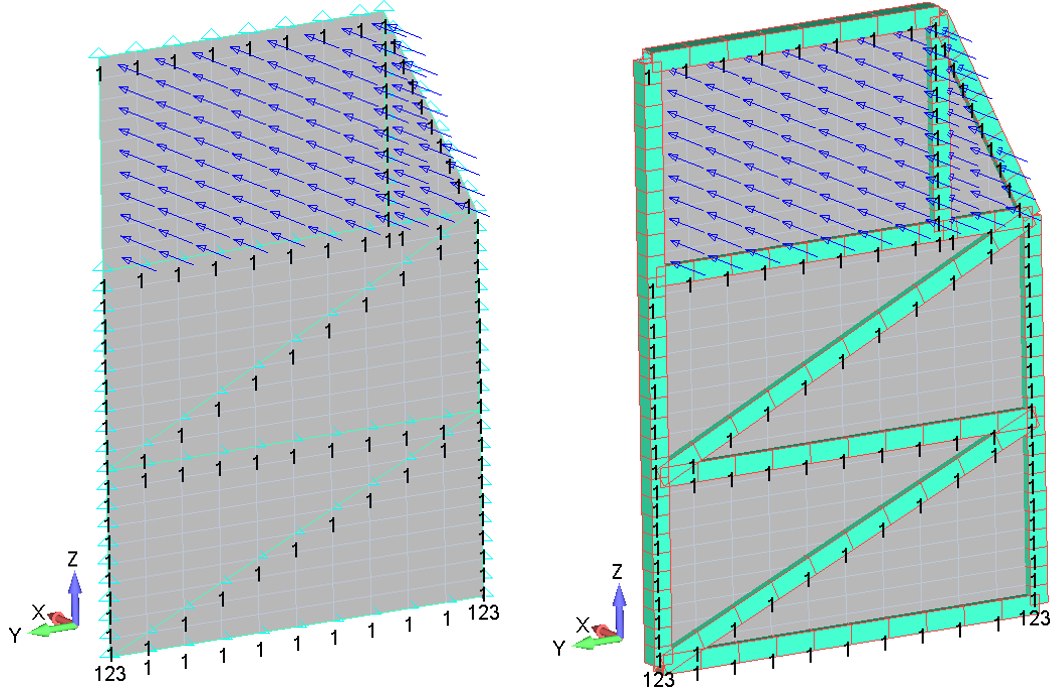
Tube frames are retained to provide realistic support stiffness and their common nodes are merged with the plate mesh. For demand, no frame load sharing is credited: the full 720 lbf forward-case load is applied to the skin.
- Tx: restrained on tube frames except at the compartment opening.
- Ty and Tz: restrained at the bottom of the local model.
The restraints eliminate rigid-body motion while leaving the opening free to deform. Restrained-node stress peaks are retained rather than de-peaked, making the check conservative.
Load Application
Two upper compartments rated at 40 lbf each are combined and multiplied by the forward 9g factor. The complete resultant is assigned to the skin panel.
Forward 9g resultant:
Applied over 206.56 in2, the equivalent uniform pressure is:
Governing load condition used for the local panel assessment.
| Case | Direction | Payload [lbf] | Load factor [g] | Applied load [lbf] | Governing basis |
|---|---|---|---|---|---|
| 1 | Forward | 80 | 9.0 | 720 | Maximum total upper-compartment demand identified in the source assessment |
No surrounding-frame load sharing is credited, so the full 720 lbf demand passes through the panel idealization.
Linear Static Analysis
- SIMCENTER NASTRAN
- SOL 101 linear static solution
- Static pressure loading
- Plate + beam local model
Principal-stress comparison
Maximum tensile and compressive principal stresses from both plate surfaces are compared with Ftu and Fcy.
Both surfaces are retained because plate bending can reverse the governing stress through the sheet thickness.
Linear-analysis principal-stress envelope. The highlighted cells represent the governing tensile and compressive principal stresses.
| AL 2024-T3 CLAD Sheet | Forward Case | Maximum Tension [ksi] | Maximum Compression [ksi] | ||
|---|---|---|---|---|---|
| Surface | Response | F1 [ksi] | F2 [ksi] | ||
| Top | Tension | 23.33 | 13.58 | 33.50 | −33.50 |
| Compression | −10.70 | −33.50 | |||
| Bottom | Tension | 33.50 | 10.70 | ||
| Compression | −13.58 | −23.33 | |||
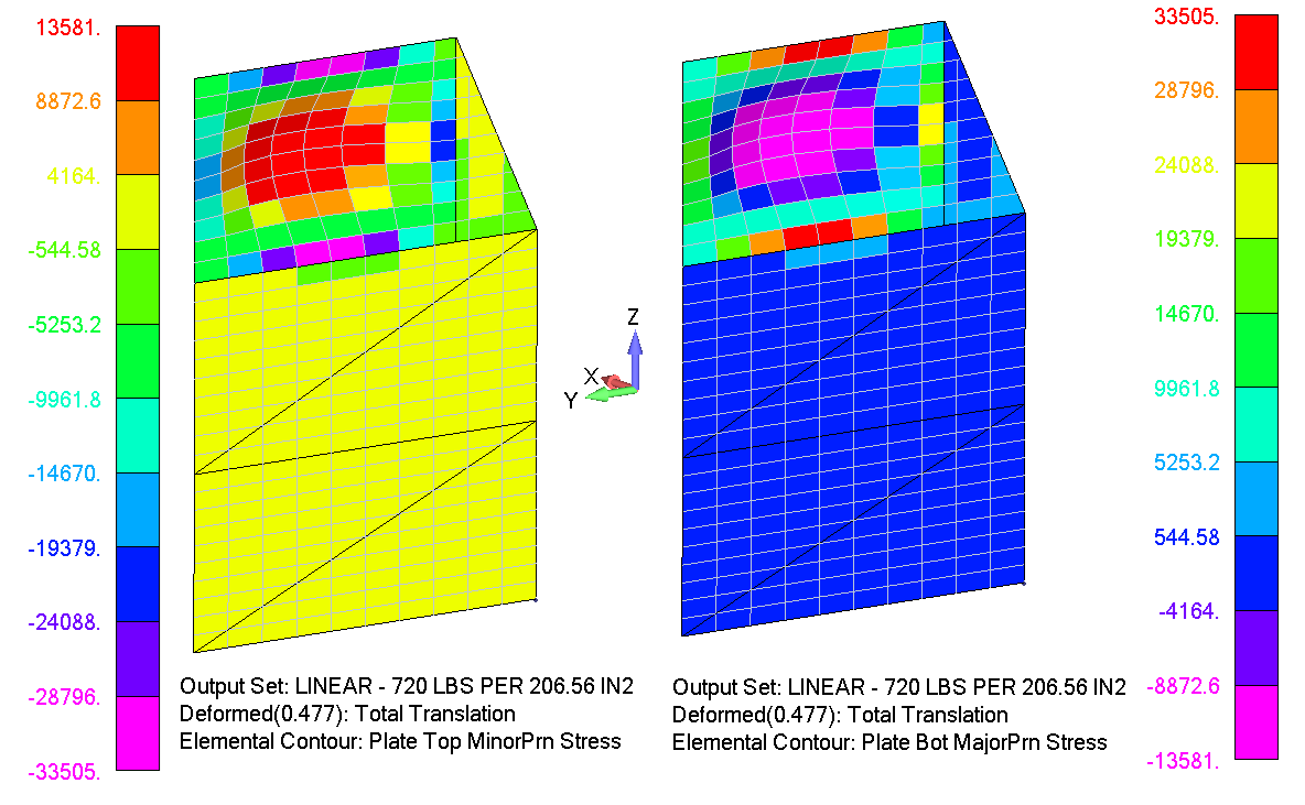
The governing peaks occur at restrained nodes. They are intentionally retained in both strength checks rather than smoothed or excluded, so the reported margins use the conservative local maxima.
Allowables: Ftu = 62 ksi; Fcy = 37 ksi.
Nonlinear Material Analysis
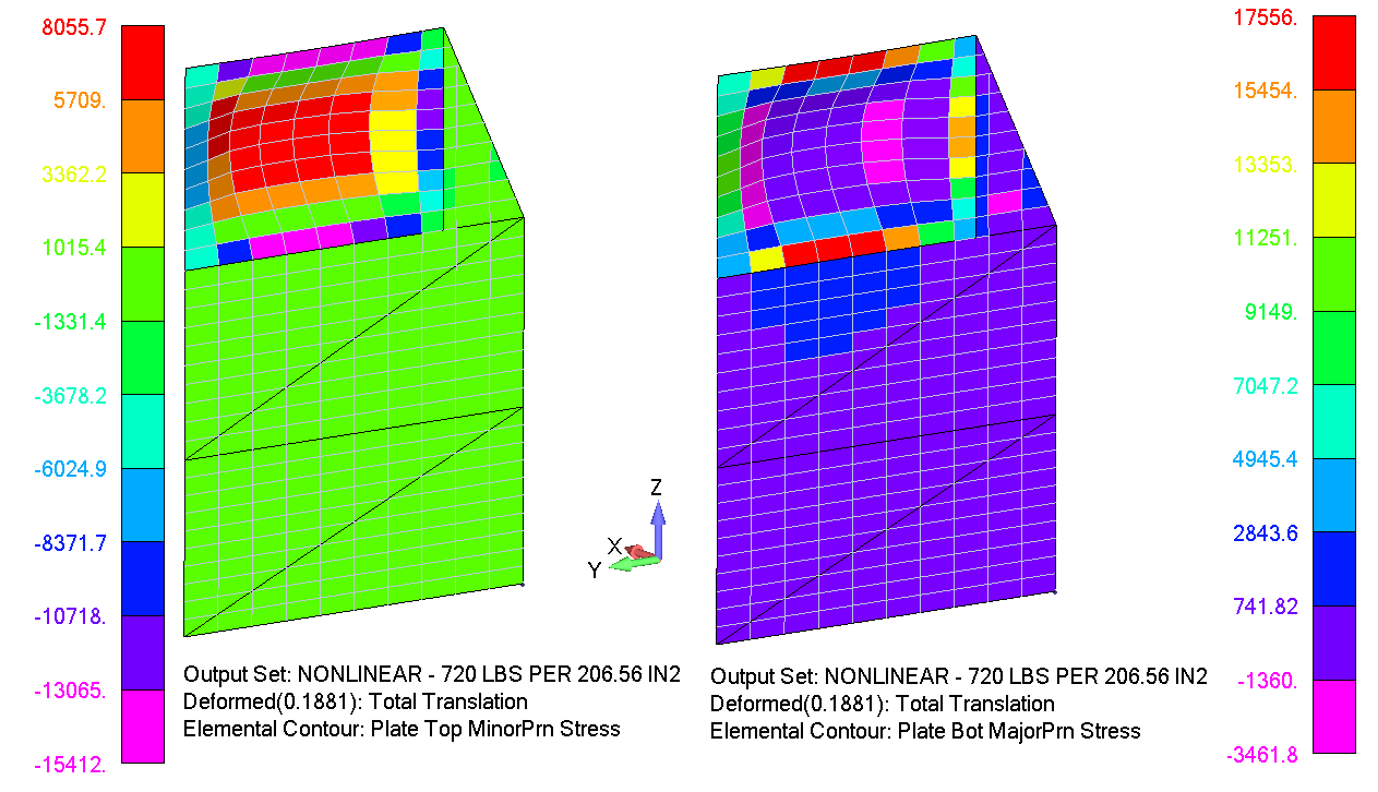
SOL 106 reuses the same mesh, restraints and pressure while replacing the elastic material law with discrete plastic stress–strain data for the panel and tube-frame alloys.
Capture post-yield stress redistribution
Material nonlinearity captures post-yield stiffness change and local stress redistribution under the same applied load.
Keeping geometry, loading and restraints unchanged isolates the effect of the material model.
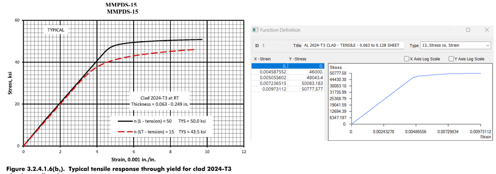
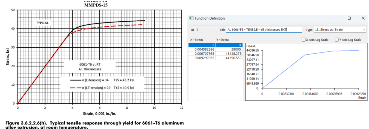
Nonlinear-analysis principal-stress envelope. The highlighted cells represent the governing tensile and compressive principal stresses.
| AL 2024-T3 CLAD Sheet | Forward Case | Maximum Tension [ksi] | Maximum Compression [ksi] | ||
|---|---|---|---|---|---|
| Surface | Response | F1 [ksi] | F2 [ksi] | ||
| Top | Tension | 9.59 | 8.06 | 17.56 | −15.41 |
| Compression | −6.33 | −15.41 | |||
| Bottom | Tension | 17.56 | 5.45 | ||
| Compression | −3.46 | −10.25 | |||
Fastener Assessment
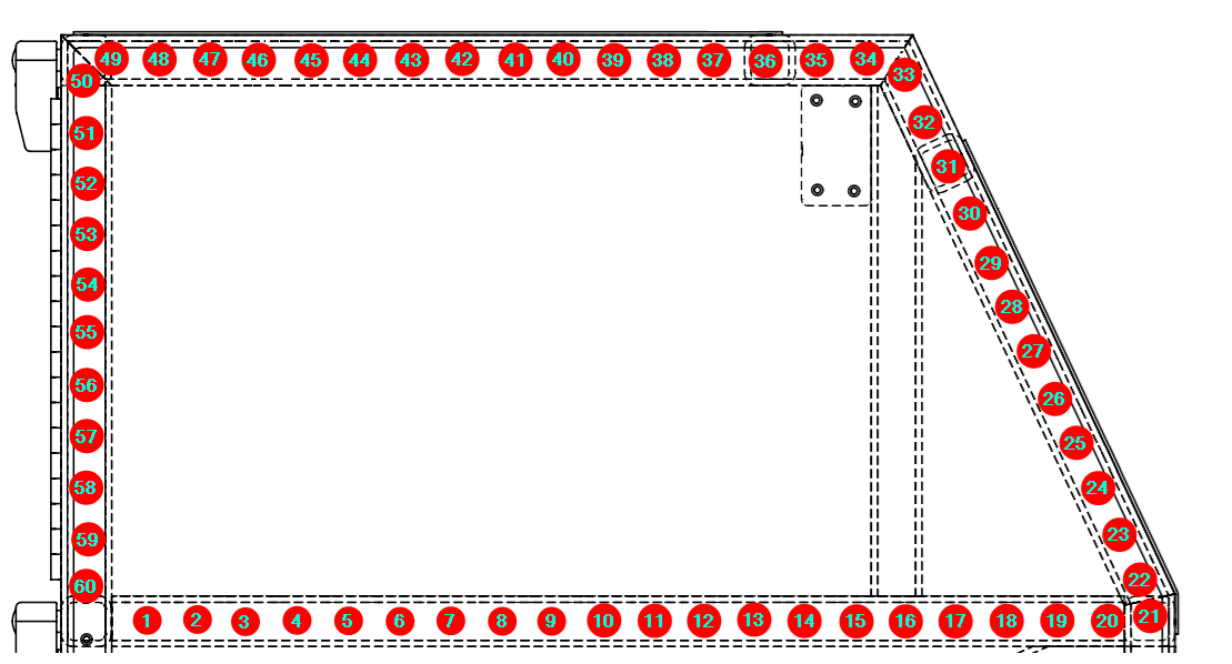
Sixty CR3212 (ARM4) rivets attach the panel region to the tube structure. Because the local model omits the adjacent joint load path, rivet capacity is checked separately instead of extracting shear directly from the FEM.
Rivet shear is not extracted from the local panel FEM
The fixed local frame and omitted adjacent structure prevent a reliable joint-shear distribution from being recovered from this model.
The full 720 lbf is therefore treated as pull-out, with only ten rivets credited equally.
Demand per credited rivet:
- Material: AL 5056 alloy
- Reference tensile strength: 285 lbf for a 0.156 in countersunk sheet
- Panel sheet thickness: 0.0625 in
- Tensile capacity scaled to the actual sheet thickness
Scaled tensile capacity for the actual panel thickness:
The source margin calculation applies an additional 1.15 multiplier to the rivet demand term:
Substantiation Outcome
All evaluated static-strength checks pass.
- Linear and nonlinear panel checks retain restrained-node hot spots and remain positive.
- The separate conservative CR3212 pull-out check also remains positive.
References
Material Allowables & Constitutive Data
- MMPDS-15 — Metallic Materials Properties Development and Standardization
Analysis Solver & Methods
- SIMCENTER NASTRAN — SOL 101 linear static and SOL 106 nonlinear static analysis