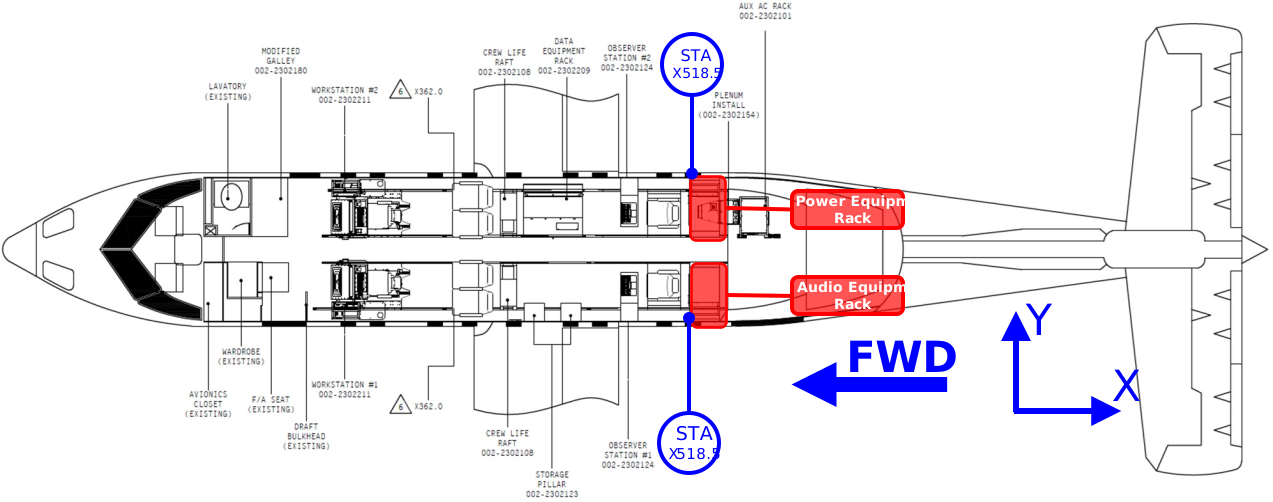
Located at X518.5 and carrying the larger installed equipment mass.
INTRODUCTION
AircraftDHC-8-100Interior equipment-rack modification
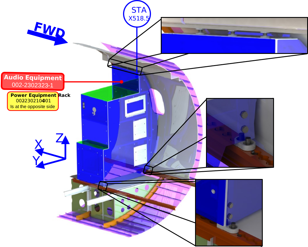
InstallationsAudio · Port / Power · StarboardCommon structural architecture at X518.5
Governing configurationAudio Equipment RackHeavier installation; Power Rack covered by comparison
Substantiation routeFEA + classical checksJoints, beams, plates, attachments and equipment support
The substantiation establishes the rack load path from installed equipment through the rack structure and attachment studs into the aircraft, then checks the critical members and joints against applicable ultimate-strength criteria.
DESIGN ASSESSMENT
General Layout
Same rack architecture and station; lower payload than the Audio rack.
The two installations share the same structural design and fuselage station, so the heavier rack envelopes the common structural response.
The Power Rack is substantiated by comparison to the heavier Audio Rack rather than duplicating an equivalent FE assessment.
Governing-model decision
The Audio Equipment Rack is selected for detailed substantiation because its higher installed mass produces the conservative inertial demand for two otherwise equivalent rack structures.
I used the heavier Audio Equipment Rack as the governing global model because both racks share the same structural architecture and installation station, while the Audio rack carries the larger equipment mass. Equipment inertia is introduced into the tube frame through RBE3-connected point masses so the payload is transferred without adding artificial stiffness. Removed panels, small hardware, and other non-structural items are recovered as distributed non-structural mass on the tube structure. The global load path therefore runs from equipment and distributed mass into the rack frame, then through the upper and lower stud attachments into the aircraft structure. The upper attachment bracket is assessed in a separate local FE model because its detailed geometry and local stress question require more resolution than the global rack model.
Audio Equipment Rack Components
The rack combines AL 6061-T6 tube/extrusion load-carrying members with AL 2024-T3 sheet components. The following tables retain the source geometry, thicknesses and material allowables used in the substantiation.
Main structural components, material and thickness.
| Component | Thickness (in) |
Material |
|---|---|---|
| Upper Attachment Bracket | 0.125 | AL 2024-T3 CLAD Sheet |
| Upper Attachment Shim | ||
| Shims | ||
| Upper Mounting Plate | ||
| INBD Step Panel | 0.071 | |
| Top Panel | ||
| AFT Grill Cover Plate | ||
| CB Panel Shim | ||
| Avionics Shelf Plate | 0.0625 | |
| Grounding Bracket | ||
| Mid Shelf Mounting Plate | ||
| HF Mounting Plate | ||
| 3G-AMA Mounting Bracket | ||
| RT7000 Mounting Plate | ||
| Network Switch Brackets | ||
| Fan Shim | ||
| FWD Access Panel | ||
| Fire Port Shim | ||
| CB Door Shim | ||
| CB Door | ||
| CB Lexan Clip | ||
| CB Back Panel | ||
| CB Panel | ||
| CB Side Angle | ||
| CB Side Clip | ||
| AFT Grill Shim | ||
| Exhaust Fan Mounting Bracket and Clip | ||
| Fire Port Cover and Stop | 0.05 | |
| Upper Support Clip | ||
| AFT and FWD Panels | 0.032 | |
| INBD Lower, Mid, and Top Panels | ||
| OUTBD Upper Panel | ||
| INBD Access Panel | ||
| Upper Support Angle | 0.25 | AL 6061-T6 Extrusion |
| Angle, Unequal Leg Extrusion | 0.156 | |
| Vertical Support Angle | 0.125 | |
| Mid Shelf Horizontal Angle | ||
| Unequal Leg Extrusion Angles | ||
| Lift Mount Angle | ||
| Equal Leg Extrusion Angle | 0.063 | |
| Camloc Clip | ||
| Top Support Angle | ||
| Square Tube | 0.125 | AL 6061-T6 Tube |
| CB Lexan Cover | 0.125 | LEXAN 9604 |
| Neoprene Stopper | 0.625 | NEOPRENE |
Material properties used in the Audio Equipment Rack [MMPDS-15- Table 3.6.2.0(c1), Table 3.6.2.0(g), Table 3.2.4.0(c1)].
AL 6061-T6 Tube t=0.025” – 0.5” |
AL 6061-T6 Extrusion t≤1” |
AL 2024-T3 CLAD Sheet t=0.01” – 0.062” |
AL 2024-T3 CLAD Sheet t=0.063” – 0.128” |
Direction | Unit | |
|---|---|---|---|---|---|---|
| Ftu | 42 | 38 | 60 | 62 | L | ksi |
| - | 37 | 59 | 61 | LT | ksi | |
| Fty | 35 | 35 | 44 | 45 | L | ksi |
| - | 33 | 39 | 40 | LT | ksi | |
| Fcy | 34 | 34 | 36 | 37 | L | ksi |
| - | 35 | 42 | 43 | LT | ksi | |
| Fsu | 27 | 26 | 37 | 38 | - | ksi |
| Fbru | 67 | 64 | 97 | 101 | e/D=1.5 | ksi |
| 88 | 82 | 121 | 125 | e/D=2 | ksi | |
| Fbry | 49 | 54 | 68 | 70 | e/D=1.5 | ksi |
| 56 | 60 | 82 | 84 | e/D=2 | ksi | |
| E x103 | 9.9 | 9.90 | 10.50 | 10.50 | - | ksi |
| Ec x103 | 10.10 | 10.10 | 10.70 | 10.70 | - | ksi |
| μ | 0.33 | 0.33 | 0.33 | 0.33 | - | - |
| ρ | 0.098 | 0.098 | 0.1 | 0.1 | - | lbm/in3 |
| G x103 | 3.8 | 3.80 | - | - | - | ksi |
Fasteners Allowables
Joint allowable philosophy
Use the weakest applicable failure path for the actual fastener / sheet stack-not the isolated fastener strength.
Sheet thickness and material can govern joint strength.Countersunk geometry is checked with the applicable static-joint reduction.Rivet tension is checked only when a meaningful tensile reaction exists.
Why the joint-not the catalog fastener-governs. A fastener installed through finite-thickness sheets shares load with the surrounding material. Bearing, countersunk geometry, local stiffness and sheet thickness can therefore reduce the usable joint load below the isolated fastener capacity.
Mechanical Properties for the fasteners used in the Audio Equipment Rack installation [NAS528 Fastener Codes, CHERRYMAX Rivets-Specs, MS24693-Specs, MS35206-Specs, NAS1801-Specs, NASM525-Specs, NAS8602-Specs, NASM3-20-Specs, FE200744-Specs, MMPDS-15-table 8.1.2(a) and (b), Table 9.7.1.1, Table 8.1.1.2, Table 8.1.5(b1) and (b2), Analysis & Design of Flight Vehicle Structures-Bruhn-Table D1.1].
| P/N | Type | Head | Size (Callout)(Thread)(Length) |
Material | (Dr)(Ds)(Dn) (in) |
(Fsu)(Ftu) for fastener material [ksi] |
(fsu)(ftu) for fastener in single shear [lbf] |
Thread Standard |
|---|---|---|---|---|---|---|---|---|
| MS20426AD4 | Solid Rivet | CSK | (BB) (-) (-) | AL 2117-T3 | (0.125)(-)(0.1285) | (30)(-) | (389)(-) | - |
| MS20470AD4 | Solid Rivet | Protruded | (BJ)(-)(-) | (0.125)(-)(0.1285) | (30)(-) | (389)(-) | - | |
| CR3212 | Blind Rivet | CSK | (ARM)(-)(-) | AL 5056 | (0.125)(-)(0.1285) | (50)(-) | (664)(285) | - |
| CR3213 | Blind Rivet | Protruded | (ARN)(-)(-) | (0.125)(-)(0.1285) | (50)(-) | (664)(285) | - | |
| MS24693-S273 | Screw | CSK | (#10-32)(UNF-2A)(0.625) | Carbon Steel, Cadmium Plated | (-)(0.19)(-) | (0.6x60)(60) | (-)(1200) | MIL-S-7742 |
| MS24693-S6 | Screw | CSK | (#4-40)(UNC-2A)(0.5) | (-)(0.112)(-) | (0.6x60)(60) | (-)(360) | MIL-S-7742 | |
| MS35206-331 | Screw | Pan | (#8-32)(UNC-2A)(0.562) | (-)(0.164)(-) | (0.6x60)(60) | (-)(840) | MIL-S-7742 | |
| NAS1801-08-10 | Screw | Hex | (#8-32)(UNJC-3A)(0.625) | Alloy Steel, Cadmium Plated | (-)(0.164)(-) | (0.6x160)(160) | (-)(-) | MIL-S-8879 |
| NAS1801-08-16 | Screw | Hex | (#8-32)(UNJC-3A)(1) | (-)(0.164)(-) | (0.6x160)(160) | (-)(-) | MIL-S-8879 | |
| NAS1801-3-10 | Screw | Hex | (#10-32)(UNJF-3A)(0.625) | (-)(0.19)(-) | (0.6x160)(160) | (-)(-) | MIL-S-8879 | |
| NAS1801-4-12 | Screw | Hex | (#1/4-28)(UNJF-3A)(0.75) | (-)(0.25)(-) | (0.6x160)(160) | (-)(-) | MIL-S-8879 | |
| NAS1801-3-9 | Screw | Hex | (#10-32)(UNJF-3A)(0.5625) | (-)(0.19)(-) | (0.6x160)(160) | (-)(-) | MIL-S-8879 | |
| AN525-832-8 | Screw | Washer | (#8-32)(-)(0.5) | (-)(0.164)(-) | (0.6x125)(125) | (-)(-) | MIL-S-7742 | |
| AN525-832-9 | Screw | Washer | (#8-32)(-)(0.5625) | (-)(0.164)(-) | (0.6x125)(125) | (-)(-) | MIL-S-7742 | |
| NAS8602-6 | Bolt | CSK | (#8-32)(UNJC-3A)(0.375) | (-)(0.164)(-) | (95)(160) | (-)(-) | MIL-S-8879 | |
| AN4-14A | Aircraft Bolt | Hex | (#1/4-28)(UNF-3A)(1.53125) | Non-Corrosion Resistant Steel | (-)(0.25)(-) | (-)(-) | (3680)(4080) | MIL-S-7742 |
| AN3-26A | Aircraft Bolt | Hex | (#10-32)(UNF-3A)(2.78125) | (-)(0.19)(-) | (-)(-) | (2125)(2210) | MIL-S-7742 | |
| 002-2302575-1 | Upper Attachment Stud | - | (3/8-24)(-)(-) | Steel, Cadmium Plated | (-)(0.375)(-) | (-)(-) | (4,000)(4,000) | - |
| 2600-4W | Camloc Stud | Wing | - / - / - | - | - | (-)(-) | (200)(300) | - |
| 2700-4S | Camloc Stud | CSK | - / - / - | - | - | (-)(-) | (200)(300) | - |
| FE200744 | Lower attachment Stud | - | (3/8-24)(UNRF)(0.9) | Carbon steel, Zinc Plated | (-)(0.375)(-) | (-)(-) | (2,000)(5,000) | - |
Summary of the joint configurations utilized in the Audio Equipment Rack. A: AL 2024-T3 ALCLAD Sheet, B: AL 6061-T6 Extrusion, C: AL 6061-T6 Extrusion
Joint No. |
Fastener Type | P/N | Layer 1 | Layer 2 | Layer 3 | |||
|---|---|---|---|---|---|---|---|---|
| Material | t (in) | Material | t (in) | Material | t (in) | |||
| 1 | Upper Attachment Stud | 002-2302575-1 | A | 0.125 | A | 0.125 | ||
| 2 | Wing Camloc Stud | 2600-4W | A | 0.0625 | A | 0.032 | ||
| 3 | A | 0.0625 | A | 0.071 | ||||
| 4 | CSK Camloc Stud | 2700-4S | A | 0.032 | A | 0.032 | ||
| 5 | A | 0.032 | B | 0.063 | ||||
| 6* | Machine Aircraft Bolt (#10-32) | AN3-26A | A | 0.125 | B | 0.125 | ||
| 7* | Machine Aircraft Bolt (#1/4-28) | AN4-14A | A | 0.032 | C | 0.125 | ||
| 8* | Washer Head Screw (#8-32) | AN525-832-8 | A | 0.0625 | B | 0.125 | ||
| 9 | Washer Head Screw (#8-32) | AN525-832-9 | B | 0.125 | ||||
| 10 | Rivet | CR3212 | A | 0.0625 | C | 0.125 | ||
| 11 | A | 0.071 | C | 0.125 | ||||
| 12 | Rivet | CR3213 | A | 0.05 | A | 0.0625 | C | 0.125 |
| 13 | A | 0.05 | C | 0.125 | ||||
| 14 | A | 0.0625 | A | 0.0625 | ||||
| 15 | A | 0.0625 | C | 0.125 | ||||
| 16 | B | 0.063 | A | 0.125 | C | 0.125 | ||
| 17 | B | 0.063 | C | 0.125 | ||||
| 18 | B | 0.125 | A | 0.125 | ||||
| 19 | B | 0.125 | B | 0.125 | ||||
| 20 | A | 0.125 | B | 0.125 | ||||
| 21 | B | 0.156 | B | 0.125 | ||||
| 22 | B | 0.25 | A | 0.0625 | B | 0.125 | ||
| 23 | B | 0.25 | B | 0.125 | ||||
| 24 | B | 0.063 | B | 0.063 | C | 0.125 | ||
| 25 | SINGLE STUD FITTING | FE200744 | ||||||
| 26 | Rivet | MS20426AD | A | 0.032 | ||||
| 27 | A | 0.05 | B | 0.063 | A | 0.071 | ||
| 28 | A | 0.0625 | A | 0.032 | ||||
| 29 | A | 0.0625 | A | 0.0625 | A | 0.0625 | ||
| 30 | A | 0.0625 | B | 0.063 | ||||
| 31* | A | 0.0625 | ||||||
| 32 | A | 0.071 | A | 0.0625 | ||||
| 33* | B | 0.125 | ||||||
| 34* | A | 0.0625 | ||||||
| 35* | Rivet | MS20470AD | A | 0.032 | ||||
| 36 | A | 0.0625 | A | 0.0625 | ||||
| 37 | B | 0.125 | B | 0.125 | ||||
| 38 | B | 0.25 | B | 0.125 | ||||
| 39 | Flat Countersunk Screw (#10) | MS24693-S273 | A | 0.0625 | B | 0.125 | ||
| 40* | A | 0.125 | B | 0.125 | ||||
| 41* | B | 0.125 | ||||||
| 42* | Flat Countersunk Screw (#4-40) | MS24693-S6 | B | 0.156 | ||||
| 43 | Machine-Pan Head Screw (#8-32) | MS35206-331 | A | 0.0625 | A | 0.0625 | ||
| 44* | Hex Head Cruciform Recess Screw (#8-32) | NAS1801-08-10 | B | 0.125 | ||||
| 45* | Hex Head Cruciform Recess Screw (#8-32) | NAS1801-08-16 | B | 0.125 | ||||
| 46* | Hex Head Cruciform Recess Screw (#10-32) | NAS1801-3-10 | A | 0.125 | B | 0.125 | ||
| 47 | Hex Head Cruciform Recess Screw (#10-32) | NAS1801-3-9 | A | 0.0625 | A | 0.0625 | A | 0.0625 |
| 48 | Hex Head Cruciform Recess Screw (#1/4-28) | NAS1801-4-12 | A | 0.125 | B | 0.25 | ||
In rivets, the standard methods of stress analyses of riveted joints consider two primary types of failure, namely, the (i) shear of the rivet’s shank, and the (ii) bearing or compressive failure of the metal at the point where the rivet bears against the connecting sheet or plate.
The tension on rivets shall be restricted to conditions in which tension load is minor compared with the shear load, which is the main purpose of the rivet. If this is not the case, the rivet tension allowable should be determined.
MS20426AD4 rivet
MS20426AD4 · Countersunk solid rivet
MaterialAL 2117-T3Material shear allowableFsu = 30 ksiNominal single shear389 lbfConfigurationsSingle + double shearPrimary checksStatic joint shear + bearingTensionNot governing in the assessed rivet joints
In the Audio Equipment Rack assembly, the tensile load carried by the MS20426AD4 rivets within all joints are minor compared with the shear load. Therefore, the tension failure is not critical for the MS20426AD4 rivets and will not be checked. The shear and bearing allowables for the MS20426AD4 rivets will be calculated, and the lowest among them will be chosen as the joint allowable for the MS20426AD4 rivet-sheet configuration.
The MS20426AD4 rivet is utilised at various locations within the Audio Equipment Rack assembly with different configurations. As illustrated in the corresponding table, the rivet was used in a single shear state at joints J3-J9 and in a double shear state at joints J1 and J2.
MS20426AD4 Rivets’ Joints in the Audio Equipment Rack assembly.
| Joint | Layer 1 | Layer 2 | Layer 3 | |||
|---|---|---|---|---|---|---|
| Material | t (in) |
Material | t (in) |
Material | t (in) |
|
| J1 | A | 0.0625 | A | 0.0625 | A | 0.0625 |
| J2 | A | 0.05 | B | 0.063 | A | 0.071 |
| J3 | A | 0.0625 | A | 0.032 | ||
| J4 | A | 0.0625 | A | 0.0625 | ||
| J5 | A | 0.071 | A | 0.0625 | ||
| J6 | A | 0.0625 | B | 0.063 | ||
| J7* | A | 0.032 | ||||
| J8* | A | 0.0625 | ||||
| J9* | B | 0.125 | ||||
A: AL 2024-T3 ALCLAD Sheet B: AL 6061-T6 Extrusion * Pass through an equipment flange as well, but conservatively, this flange has been ignored. |
||||||
(i) Shear of the Rivet’s Shank:
Installed-rivet effect. Joint strength is evaluated in the actual sheet stack because hole bearing, sheet thickness, countersunk geometry and local stiffness redistribute load and can reduce the usable rivet shear capacity.
As shown in the corresponding table, the MS20426AD4 is made from AL 2117-T3 alloy that has an ultimate shearing strength Fsu = 30 ksi, and rivet single shear strength value of fsu=389 lbf (for 1/8 rivet size). As illustrated in the corresponding table, the rivets in the joints J1 – J2, and J3 - J8 are in double and single shear state, respectively, and the CSK sheet in these joints is made from AL 2024-T3 ALCLAD sheet. Therefore, the joints’ shear strength is determined using [MMPDS-15- Table 8.1.2.2(o)] (considering the CSK sheet thickness) and tabulated in the corresponding table.
In joint J9, the CSK sheet is made from 0.125” thick AL 6061-T6 Extrusion. There is no table for the Static Joint Strength for this material type. Although the CSK sheet is thick enough to consider the ultimate single shear strength value as the joint allowable, the ultimate single shear strength value is scaled down, conservatively, by a factor of 1.5. As a result, the estimated ultimate shear strength of that joint is 389/1.5=259 lbf.
(ii) Joint Bearing strength:
When considering a countersunk rivet joining two sheets of different thicknesses, especially when the countersunk portion does not engage with the thinner sheet(s), the calculation of ultimate joint stress with a focus on bearing stress becomes particularly important since the mechanical interlock provided by the rivet is primarily with the thicker sheet. Moreover, the load transfer mechanism relies heavily on the bearing stress between the rivet shank and the hole in the thinner sheet. The ultimate bearing stress calculation became critical to ensure that the material of the thinner sheet around the rivet hole can withstand the compressive load exerted by the rivet without yielding or failing.
The non-CSK sheet is thinner than the CSK sheet in joints J3 and J5. Also, the joints J7, J8, and J9 involve equipment flange that were conservatively omitted. For these joints the Joint Bearing Strength must be calculated using the non-CSK sheet thickness and compared with the Static Joint Strength calculated previously and the smaller value will be considered as the joint allowable. The non-CSK sheets in joints J3, J5, J7, and J8, are AL 2024-T3 ALCLAD, and it has an ultimate bearing strength of 121 ksi (refer to the corresponding table). The non-CSK sheet in the joint J9 is AL 6061-T6 Extrusion, and it has an ultimate bearing strength of 82 ksi (refer to the corresponding table). Hence, the ultimate bearing strength for these joints can be calculated using [MMPDS-15- Table 8.1.2.1(a)] by multiplying the Joint Bearing strength for Fbr=100 ksi by the ratio of actual bearing strength to 100 ksi. The results are listed in the corresponding table. It is noteworthy that the rest of the joints have a non-CSK sheet thickness ≥ the CSK sheet thickness. Hence, calculating the joint ultimate bearing strength is not required for these joints.
MS20426AD4 joint allowables in the Audio Equipment Rack assembly.
| Joint | Layer 1 | Layer 2 | Layer 3 | fsu [lbf] |
fbru [lbf] |
fjoint [lbf] |
Failure Mode |
|||||
|---|---|---|---|---|---|---|---|---|---|---|---|---|
| Material | t (in) |
Material | t (in) |
Material | t (in) |
|||||||
| J1 | A | 0.0625 | A | 0.0625 | A | 0.0625 | 389 x 2 | 778 | - | - | 778 | Shear |
| J2 | A | 0.05 | B | 0.063 | A | 0.071 | 380 x 2 | 760 | - | - | 760 | Shear |
| J3 | A | 0.0625 | A | 0.032 | 389 x 1 | 389 | 121/100 x 411 | 497.31 | 389 | Shear | ||
| J4 | A | 0.0625 | A | 0.0625 | 389 x 1 | 389 | - | - | 389 | Shear | ||
| J5 | A | 0.071 | A | 0.0625 | 389 x 1 | 389 | 121/100 x 810 | 980.1 | 389 | Shear | ||
| J6 | A | 0.0625 | B | 0.063 | 389 x 1 | 389 | - | - | 389 | Shear | ||
| J7* | A | 0.032 | 263 x 1 | 263 | 121/100 x 411 | 497.31 | 263 | Shear | ||||
| J8* | A | 0.0625 | 389 x 1 | 389 | 121/100 x 810 | 980.1 | 389 | Shear | ||||
| J9* | B | 0.125 | 259 x 1 | 259 | 82/100 x 1606 | 1316.92 | 259 | Shear | ||||
A: AL 2024-T3 ALCLAD Sheet B: AL 6061-T6 Extrusion * Pass through an equipment flange as well, but conservatively, this flange has been ignored. |
||||||||||||
CR3212 rivet
CR3212 · Countersunk blind rivet
MaterialAL 5056Material shear allowableFsu = 50 ksiNominal single shear664 lbfTensile capacity285 lbfJoint stateSingle shearGoverning logicCSK static-joint strength
In the Audio Equipment Rack assembly, the tensile load carried by the CR3212 rivets within all joints are minor compared with the shear load. Therefore, the tension failure is not critical for the CR3212 rivets and will not be checked. The shear and bearing allowables for the CR3212 rivets will be calculated, and the lowest among them will be chosen as the joint allowable for the CR3212 rivet-sheet configuration.
As illustrated in the corresponding table, the CR3212 rivet is utilised at two locations within the Audio Equipment Rack assembly with different configurations, but in both configurations the rives are used in a single shear state.
CR3212 Rivets’ Joints in the Audio Equipment Rack assembly.
| Joint | Layer 1 | Layer 2 | ||
|---|---|---|---|---|
| Material | t (in) |
Material | t (in) |
|
| J1 | A | 0.071 | C | 0.125 |
| J2 | A | 0.0625 | C | 0.125 |
A: AL 2024-T3 ALCLAD Sheet C: AL 6061-T6 Extrusion |
||||
(i) Shear of the Rivet’s Shank:
Installed-rivet effect. Joint strength is evaluated in the actual sheet stack because hole bearing, sheet thickness, countersunk geometry and local stiffness redistribute load and can reduce the usable rivet shear capacity.
Based on the corresponding table, the CR3212 is made from AL 5056 alloy that has an ultimate shearing strength Fsu = 50 ksi, and rivet single shear strength value of fsu=664 lbf (for 1/8 rivet size). As illustrated in the corresponding table, the rivets in the joints J1 – J2 are in single shear state, and the CSK sheet in these joints is made from AL 2024-T3 ALCLAD sheet. Therefore, the joint’s shear strength using the CSK sheet thickness is determined using [MMPDS-15-Table 8.1.3.2.2(v)] and tabulated in the corresponding table. It is noteworthy that the values in [Table 8.1.3.2.2(v)] are for Fsu=51 ksi, so the joint’s shear strength was scaled down by a factor of 50/51.
(ii) Joint Bearing strength:
The non-CSK sheet is thicker than the CSK sheet in both joints. Therefore, calculating the joint ultimate bearing strength is not required [MMPDS-15].
CR3212 joint allowables in the Audio Equipment Rack assembly.
| Joint | Layer 1 | Layer 2 | fsu [lbf] |
fbru [lbf] |
fjoint [lbf] |
Failure Mode |
||||
|---|---|---|---|---|---|---|---|---|---|---|
| Material | t (in) |
Material | t (in) |
|||||||
| J1 | A | 0.071 | C | 0.125 | 437x(50/51) | 428 | - | - | 437 | Shear |
| J2 | A | 0.0625 | C | 0.125 | 401x(50/51) | 393 | - | - | 401 | Shear |
A: AL 2024-T3 ALCLAD Sheet C: AL 6061-T6 Extrusion |
||||||||||
MS20470AD4 rivet
MS20470AD4 · Protruding-head solid rivet
MaterialAL 2117-T3Nominal single shear389 lbfJoint stateSingle shear in assessed configurationsThickness sensitivityDr/tmin checkedCorrectionApplied where Dr/tmin exceeds the MMPDS criterionGoverning logicmin(shear, bearing)
In the Audio Equipment Rack assembly, the tensile load carried by the MS20470AD4 rivets within all joints are minor compared with the shear load. Therefore, the tension failure is not critical for the MS20470AD4 rivets and will not be checked. The shear and bearing allowables for the MS20470AD4 rivets will be calculated, and the lowest among them will be chosen as the joint allowable for the MS20470AD4 rivet-sheet configuration.
The MS20470AD4 rivet is utilised at various locations within the Audio Equipment Rack assembly with different configurations. As illustrated in the corresponding table, the rivet was used in a single shear state at all joints, namely, J1-J6.
MS20470AD4 Rivets’ Joints in the Audio Equipment Rack assembly.
| Joint | Layer 1 | Layer 2 | Dr/tmin | ||
|---|---|---|---|---|---|
| Material | t (in) |
Material | t (in) |
||
| J1 | A | 0.0625 | A | 0.0625 | 2.00 |
| J2 | A | 0.0625 | A | 0.0625 | 2.00 |
| J3 | B | 0.125 | B | 0.125 | 1.00 |
| J4 | B | 0.25 | B | 0.125 | 1.00 |
| J5* | A | 0.032 | 3.91 | ||
| J6 | A | 0.125 | A | 0.125 | 1.00 |
A: AL 2024-T3 ALCLAD Sheet B: AL 6061-T6 Extrusion * Pass through an equipment flange as well, but conservatively, this flange has been ignored. |
|||||
(i) Shear of the Rivet’s Shank:
Installed-rivet effect. Joint strength is evaluated in the actual sheet stack because hole bearing, sheet thickness, countersunk geometry and local stiffness redistribute load and can reduce the usable rivet shear capacity.
As illustrated in the corresponding table, the rivets at all joints are in single shear state and have Dr/tmin ratios < 3, except for J5 where Dr/tmin ratio is 3.91. Therefore, a correction factor, , must be calculated for J5 to compensate for the reduction in the rivet shear strength resulting from hight bearing stresses on the rivet in this case [MMPDS-15]. The correction factor in a single shear joint can be expressed as below:
Therefore, the correction factors for the joints J5 can be calculated as below:
→
Based on [MMPDS-15-Table 8.1.2(b)], the Ultimate Single Shear Strength, fsu, for the MS20470AD4 rivet can be tabulated as in the corresponding table.
(ii) Joint Bearing strength:
For these joints shown in the corresponding table, the Joint Bearing Strength will be calculated using the thinnest sheet material. Then it will be compared with the Ultimate Single Shear Strength calculated previously and the smaller value will be considered as the joint allowable.
The thinnest sheet in the joints J1, J2, J5, and J6 is AL 2024-T3 ALCLAD that has an ultimate bearing strength of 121 ksi (refer to the corresponding table). The thinnest sheet in the joints J3 and J4 is AL 6061-T6 Extrusion that has an ultimate bearing strength of 82 ksi (refer to the corresponding table). Hence, using [MMPDS-15-Table 8.1.2.1(a)], the ultimate bearing strength for these joints can be calculated by multiplying the values from that table by the ratio of actual bearing strength to 100 ksi. The results are listed in the corresponding table.
MS20470AD4 joint allowables in the Audio Equipment Rack assembly.
| Joint | Layer 1 | Layer 2 | fsu [lbf] |
fbru [lbf] |
fjoint [lbf] |
Failure Mode | ||||
|---|---|---|---|---|---|---|---|---|---|---|
| Material | t (in) |
Material | t (in) |
|||||||
| J1 | A | 0.0625 | A | 0.0625 | 389 | 389 | 121/100 x 810 | 980.1 | 389 | Shear |
| J2 | A | 0.0625 | A | 0.0625 | 389 | 389 | 121/100 x 810 | 980.1 | 389 | Shear |
| J3 | B | 0.125 | B | 0.125 | 389 | 389 | 82/100 x 1606 | 1316.92 | 389 | Shear |
| J4 | B | 0.25 | B | 0.125 | 389 | 389 | 82/100 x 1606 | 1316.92 | 389 | Shear |
| J5* | A | 0.032 | 389 x 0.964 | 375 | 121/100 x 411 | 497.31 | 375 | Shear | ||
| J6 | A | 0.125 | A | 0.125 | 389 | 389 | 121/100 x 1606 | 1943.26 | 389 | Shear |
A: AL 2024-T3 ALCLAD Sheet B: AL 6061-T6 Extrusion * Pass through an equipment flange as well, but conservatively, this flange has been ignored. |
||||||||||
MS24693-S273 Screw
MS24693-S273 · #10-32 countersunk screw
MaterialCadmium-plated carbon steelFtu60 ksiFsu36 ksiShank diameter0.19 inThreadUNF-2ADerived capacities1,020 lbf shear · 1,200 lbf tension
The MS24693-S273 Screw is utilised at various locations within the Audio Equipment Rack assembly with different configurations. As illustrated in the corresponding table, the screw was used in single shear states at joints J1 and J3, and in double shear state in joint J2. Note that in joints J2 and J3, the screw passes through the equipment flanges EF1 and EF2, conservatively, these flanges will be omitted while determining the screw allowable. Therefore, the joint J2 will be considered as single shear joint.
MS24693-S273 Screws’ Joints in the Audio Equipment Rack assembly.
| Joint | Layer 1 | Layer 2 | Layer 3 | |||
|---|---|---|---|---|---|---|
| Material | t (in) |
Material | t (in) |
Material | t (in) |
|
| J1 | A | 0.0625 | B | 0.125 | ||
| J2* | EF1 | - | A | 0.125 | B | 0.125 |
| J3* | EF2 | - | A | 0.125 | ||
A: AL 2024-T3 ALCLAD Sheet B: AL 6061-T6 Extrusion EF1: Rt7000 EF2: ARTEMIS COMINT T1001 Mounting Tray * Pass through an equipment flange as well, but conservatively, this flange has been ignored. |
||||||
Based on the corresponding table, the #10-32 MS24693-S273 screw has the below specifications:
Material: Cadmium Plated Carbon Steel
Minimum Tensile Strength Ftu=60 ksi.
Minimum Shear Strength Fsu=36 ksi.
Length: 0.625”
Shank Diameter: 0.19”
Thread: UNF-2A
By referring to [MMPDS-15-Table 8.1.5(a) and MS24693-Specs], the Ultimate Single Shear Strength and the Ultimate Tensile Strength of the screw are fsu=992x36/35=1,020 lbf and ftu=1,200 lbf, respectively.
To determine the Joint Bearing Strength, the thinnest sheet in the joints must be used. Note that the thinnest sheet in:
J1 and J3: is made from AL 2024-T3 ALCLAD. Its ultimate bearing strength Fbru=121 ksi (refer to the corresponding table).
J2: Both sheets are made from different materials that have the same thicknesses. The sheet with the lowest Fbru value will be used, namely, AL 6061-T6 Extrusion that has an ultimate bearing strength Fbru=82 ksi (refer to the corresponding table).
Hence, using [MMPDS-15-Table 8.1.5.1], the ultimate bearing strength for these joints can be calculated by multiplying the values from that table by the ratio of actual bearing strength to 100 ksi. The results are listed in the corresponding table.
MS24693-S273 joint allowables in the Audio Equipment Rack assembly.
| Joint | Layer 1 | Layer 2 | Layer 3 | fbru [lbf] |
fsu [lbf] |
fjoint [lbf] |
||||
|---|---|---|---|---|---|---|---|---|---|---|
| Material | t (in) |
Material | [lbf] | Material | t (in) |
|||||
| J1 | A | 0.0625 | B | 0.125 | 121/100 x 1197 | 1448 | 1020 | 1020 | ||
| J2* | EF1 | - | A | 0.125 | B | 0.125 | 82/100 x 2375 | 1948 | 1020 | 1020 |
| J3* | EF2 | - | A | 0.125 | 121/100 x 2375 | 2874 | 1020 | 1020 | ||
A: AL 2024-T3 ALCLAD Sheet B: AL 6061-T6 Extrusion EF1: Rt7000 EF2: ARTEMIS COMINT T1001 Mounting Tray * Pass through an equipment flange as well, but conservatively, this flange has been ignored. |
||||||||||
MS24693-S6 Screw
MS24693-S6 · #4-40 countersunk screw
MaterialCadmium-plated carbon steelFtu60 ksiFsu36 ksiShank diameter0.112 inThreadUNC-2ADerived capacities354 lbf shear · 360 lbf tension
The MS24693-S6 Screw is utilised at the USB Port. It passes through the Port flange and 0.156” thick AL 6061‑T6 Extrusion. Conservatively, only the AL 6061‑T6 Extrusion will be considered in calculating the joint allowable.
Based on the corresponding table, the #4-40 MS24693-S6 CSK screw has the below specifications:
Material: Cadmium Plated Carbon Steel
Minimum Tensile Strength Ftu=60 ksi.
Minimum Shear Strength Fsu=36 ksi.
Length: 0.5”
Shank Diameter: 0.112”
Thread: UNC-2A
By referring to [MMPDS-15-Table 8.1.5(a) and MS24693-Specs], the Ultimate Single Shear Strength and the Ultimate Tensile Strength of the screw are fsu=345x36/35=354 lbf and ftu=360 lbf, respectively.
The screw passes through 0.156” thick AL 6061-T6 Extrusion that has an ultimate bearing strength Fbru=82 ksi (refer to the corresponding table). Hence, the ultimate bearing strength for the joints can be calculated as below:
Where: is the bearing strength of the sheet material [ksi]. is the bearing area, which is the sheet thickness times the bolt shank diameter ().
Since the Ultimate Shear Strength is less than the ultimate bearing strength, the former will be the joint allowable.
FE200744 STUD
FE200744 · Lower seat-track stud
MaterialZinc-plated carbon steelSize3/8-24 UNRFUltimate shear2,000 lbfUltimate tension5,000 lbfTrack tooth2,250 lbf per toothGoverning shearStud capacity below local bearing capacity
Based on the corresponding table, the FE200744 stud is 3/8-24 UNRF screw that is made from Zinc Plated Carbon steel. It has a vertical (tension) ultimate load of 5,000 lbf, and a horizontal (shear) ultimate load of 2,000 lbf.
The FE200744 stud is utilized in a Seat Track Stud that is made from 0.125” thick AL 2024-T351 Plate. Conservatively, the Bearing Strength of 0.25” thick AL 2024-T351 Plate will be considered. Based on MMPDS-15-the corresponding table.2.4.0(b2)], the bearing strength is Fbru=119 ksi. Therefore, based on [MMPDS-15-Table 8.1.5.1], the Unit Bearing Strength of the joint is fbru=4688*119/100 = 5,578.
Since the Ultimate Shear Strength is less than the ultimate bearing strength, the former will be the joint allowable.
Track tooth allowable:
Based on [Ancra Clear Medium-Duty Aircraft Track-Anodized-40456-10-144-Specs], the seat track’s vertical load allowable is 4500 lbf. Hence, the vertical load allowable per tooth is 4500/2 = 2,250 lbf (this is the allowable reaction force exerted on the rail lip by the FE200744 lock head)
UPPER ATTACHMENT STUD
Customized upper attachment stud
Reference hardwareANCRA 40351-10 threaded studReference directional capacity4,000 lbfCritical local modeStud-head bendingConservative armLoad applied at start of full-diameter regionTrack tooth2,250 lbf per toothDesign logicUse the lower of bending / track transfer limits
The customized Upper Attachment Stud is made from the ANCRA Threaded Stud. However, its load capacity is not available. Hence, ANCRA Threaded Stud (P/N 40351-10) [40351 and 40352 Threaded Stud-Specs] will be used to determine the Upper Attachment Stud allowable.
As shown in [40351 and 40352 Threaded Stud-Specs], the load capacity for ANCRA Threaded Stud (P/N 40351-10) is 4000 lbf in any direction. Moreover, both ANCRA Threaded Studs (P/N 40352-10 & 40351-10) are made from the same material. However, only P/N 40352-10 is heat treated to 180-200 ksi per AMS-H-6875 and is made per MIL-S-6049 that has ultimate tensile strength of 125ksi.
Stud Bending:
➜
At the head of the fastener there is region that increases in diameter, and its length is approximately 0.18”. Moreover, there is a curved portion at the tip of the stud that can be discounted since the worst (and still conservative) case would be a concentrated load at the beginning of the full diameter. Consequently, the bending arm can be calculated as follows:
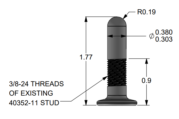
Hence, the maximum allowable shear load before bending failure
occurs, can be calculated as follows:
Track tooth allowable:
Based on [Ancra Clear Medium-Duty Aircraft Track-Anodized - 40456-10-144-Specs], the seat track’s vertical load allowable is 4500 lbf. Hence, the vertical load allowable per tooth is 4500/2 = 2,250 lbf (this is the allowable reaction force exerted on the rail lip by the stud fastener head)
SUMMARY OF ALLOWABLES
As we mentioned previously, the joint allowable is established by identifying the lowest value between fsu and fbru. Based on the previous calculations, we can set the below Joint Allowables as a benchmark in our static stress analysis.
Summary of joint allowables for the Audio Equipment Rack installation
| P/N | ftu [lbf] |
fsu [lbf] |
P/N | ftu [lbf] |
fsu [lbf] |
|---|---|---|---|---|---|
| MS20426AD4 | - | 259 | NAS1801-4-12 | 5,480 | 2,563 |
| MS20470AD4 | - | 375 | NAS1801-3-9 | 2,975 | 1,448 |
| MS20470AD5 | - | 389 | AN525-832-8 | 1,525 | 1,250 |
| CR3212 | 285 | 401 | AN525-832-9 | 1,525 | 1,580 |
| CR3213 | 285 | 422 | NAS8602-6 | 2,055 | 1,250 |
| MS24693-S273 | 1,200 | 1,020 | AN4-14A | 4,080 | 968 |
| MS24693-S6 | 360 | 354 | AN3-26A | 2,210 | 2,125 |
| MS35206-331 | 840 | 760 | 002-2302575-1 | 4000 | 481 |
| NAS1801-08-10 | 2055 | 1681 | FE200744 | 5,000 | 2,000 |
| NAS1801-08-16 | 2055 | 1681 | Track tooth | 2,250 | - |
| NAS1801-3-10 | 2975 | 1948 |
WEIGHTS
3D-model-derived weight and CoG
Modeled rack parts use the source aluminum density assumption and retain their 3D-model center-of-gravity locations.
Vendor mass + installation allowance
Equipment weights come from specification data and are scaled by 1.5 where specified to include attachment hardware and wiring/cabling.
Tube structure: 33.64 lbf
Equipment units: 79.52 lbf
Riveted panels: 4.083 lbf
Non-structural assembly: 22.913 lbf
Removable panels: 17.918 lbf
Total rack representation: 158.074 lbf
Structural and Equipment Weights for the Audio Equipment Rack.
| Component | CoG (in) |
Weight [lbf] |
|---|---|---|
| Tube Structure | 10, 11.02, 24.64 | 33.64 |
| Equipment Units | N/R | 79.52 |
| Riveted Panels | 10.03, 18.99, 39.14 | 4.083 |
| Non-Structural Assembly Parts | 8.73, 11.77, 23.23 | 22.913 |
| Non-Structural Exterior Removable Panels10 | 7.86, 15.56, 21.86 | 17.918 |
| Total: | 158.074 | |
The Non-Structural Exterior Removable Panels, the Non-Structural Assembly Parts, and Tiny Equipment Units/Parts (shown in the corresponding table) will be added to the FE model as a non-structural mass distributed over the tube structure. Its value will be WNSM=17.918 + 22.913+ 0.426 = 41.257 lbf
Small equipment items represented as non-structural mass.
| Equipment | Weight [lbf] |
Scaled Weight [lbf] |
Qty | Total [lbf] |
|---|---|---|---|---|
| RJ-45 Port | 0.094 | 0.141 | 1 | 0.141 |
| USB Port | 0.08 | 0.12 | 1 | 0.12 |
| Post Light | 0.03 | 0.045 | 3 | 0.135 |
| Switch | 0.02 | 0.03 | 1 | 0.03 |
| CB Cover | 5.15e-7 | 7.725e-07 | 1 | 7.73e-07 |
| TOTAL | 0.426 | |||
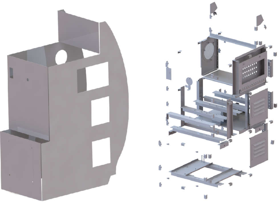
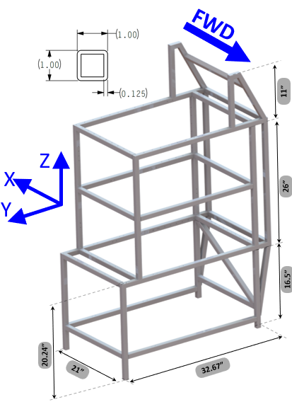
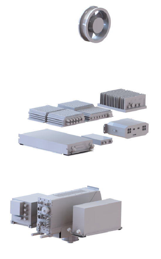
Tube Structure (TOP) Equipment Units (BOTTOM) in the Audio Equipment Rack Assembly.
the corresponding tables show the weights of the Audio Equipment Rack’s installed equipment unit, based on their specification sheets. It is noteworthy an additional estimated weight (1.5 times the component weight) has been added to each equipment to account for the weight of the hardware and wires/cables installed.
Equipment Weights on the Audio Equipment Rack.
| Equipment | Weight [lbf] |
Scaled Weight [lbf] |
Qty | Total [lbf] |
|---|---|---|---|---|
| SDI Splitter | 1.8 | 2.7 | 3 | 8.1 |
| SDI To Analog Scaling Video Converter | 1.43 | 2.145 | 1 | 2.145 |
| Makitox4 Rugged Encoder | 2.37 | 3.555 | 1 | 3.555 |
| HF Power AMP | 7.6 | 11.4 | 1 | 11.4 |
| KPA 1052 Tray | 0.8 | 1.2 | 1 | 1.2 |
| Audio Embedded Unit | 0.63 | 0.945 | 1 | 0.945 |
| Ethernet Switch | 2.8 | 4.2 | 1 | 4.2 |
| RT7000 Antenna Switching Unit | 0.35 | 0.525 | 2 | 1.05 |
| Remote Mount Tactical Radio LRU | 8.9 | 13.35 | 1 | 13.35 |
| RT7000 Mounting Tray | 1.6 | 2.4 | 1 | 2.4 |
| Artemis Comint | 9.26 | 13.89 | 1 | 13.89 |
| Artemis Comint T1001 Mounting Tray | 3.53 | 5.295 | 1 | 5.295 |
| HF Receiver/Exciter | 5.5 | 8.25 | 1 | 8.25 |
| KRX 1053 Tray | 0.4 | 0.6 | 1 | 0.6 |
| Tubeaxial Fan | 1.81 | 2.715 | 1 | 2.715 |
| RJ-45 Port | 0.094 | 0.141 | 1 | 0.141 |
| USB Port | 0.08 | 0.12 | 1 | 0.12 |
| Post Light | 0.03 | 0.045 | 3 | 0.135 |
| Switch | 0.02 | 0.03 | 1 | 0.03 |
| CB Cover | 5.15e-7 | 7.725e-07 | 1 | 7.73e-07 |
| TOTAL | 79.52 | |||
Equipment Weights on the Power Equipment Rack.
| Equipment | Weight [lbf] |
Scaled Weight [lbf] |
Qty | Total [lbf] |
|---|---|---|---|---|
| Airflow Switch | 1.00 | 1.5 | 1 | 1.500 |
| Thermostat | 0.011 | 0.017 | 1 | 0.017 |
| Pressure Switch | 0.25 | 0.375 | 1 | 0.375 |
| Limiter Fuse Block | 0.2 | 0.3 | 4 | 1.200 |
| Post Light | 0.03 | 0.045 | 4 | 0.180 |
| Switch | 0.02 | 0.03 | 1 | 0.030 |
| Circuit Breakers | 0.053 | 0.08 | 29 | 2.320 |
| AC Power Outlet | 0.3 | 0.45 | 1 | 0.450 |
| Tubeaxial Fan | 1.81 | 2.715 | 1 | 2.715 |
| True Blue Power Inverter | 7.7 | 11.55 | 1 | 11.550 |
| True Blue Power Inverter | 7.3 | 10.95 | 1 | 10.950 |
| True Blue Power Converter | 0.69 | 1.035 | 2 | 2.070 |
| Ground Fault Interrupter | 0.65 | 0.975 | 1 | 0.975 |
| TOTAL | 34.332 | |||
STATIC STRESS ANALYSIS
LOAD CASES FORMULATION
REGULATORY SOURCE BASISFAR Part 25 criteria used to formulate the structural load envelope
Flight-load framework
FAR 25.321 and 25.331–25.351
- General flight loads and symmetric maneuver response
- Flight maneuver envelope and design airspeeds
- Limit maneuver factors, gust and turbulence loads
- Fuel/oil, high-lift, rolling and yaw conditions
Emergency landing
FAR 25.561
- Forward: 9 g
- Downward: 6 g
- Upward: 3 g
- Sideward: 3 g airframe / 4 g seats & attachments
- Rearward: 1.5 g
Load-case selection. The racks sit near X529, so station-based flight accelerations are combined with the emergency-landing criteria. Five directions are retained for analysis; the 1.5 g aft case is omitted because it is enveloped by the 9 g forward case.
Vertical limit load values () at X529.21 for the upward and downward directions.
Load Direction |
X529.21 (g) |
|---|---|
| Upward | 5.52 |
| Downward | 6.02 |
These are the limit loads values. However, the ultimate load values must be used for the static stress analysis purposes. The ultimate load values () can be obtained by multiplying the limit load values by 1.5. the corresponding table lists these values.
Vertical ultimate load values () at X529.21 for the upward and downward directions.
Load Direction |
X539.5 (g) |
|---|---|
| Upward | 8.28 |
| Downward | 9.03 |
Hence, the load cases the Audio Equipment Rack will be checked against are listed in the corresponding table.
Governing ultimate load cases.
Load Case Number |
Load Factor Direction |
Ultimate Load Value () [g] |
Governing basis |
|---|---|---|---|
| 1 | Up | 8.28 | Flight |
| 2 | Down | 9.03 | Flight |
| 3 | Outboard | 3.0 | Emergency landing |
| 4 | Inboard | 3.0 | Emergency landing |
| 5 | Forward | 9.0 | Emergency landing |
| Not required | Aft | 1.5✝ | Covered conservatively by Forward case |
| ✝ This case is covered by the 9G Forward case, so it will not be required. | |||
I compared the applicable flight and emergency-landing demands direction by direction and retained only the governing condition. Flight loading governs the vertical directions at the rack station, giving 8.28 g upward and 9.03 g downward ultimate acceleration. FAR 25.561 emergency-landing loading governs the 3.0 g outboard, 3.0 g inboard, and 9.0 g forward directions. The 1.5 g aft condition is not modeled separately because it is conservatively enveloped by the 9.0 g forward case. This produces five traceable certification load cases without duplicating non-governing conditions.
FINITE ELEMENT ANALYSIS (FEA)
Audio Rack envelopes the Power Rack
Both racks use the same structural design at the same fuselage station. The Audio Rack is approximately 45 lbf heavier, so its inertial response is used to substantiate the common rack architecture.
MODEL
Square tube structure
The welded square-tube frame is modeled with beam elements so section area, inertia, axial force, shear and bending are recovered efficiently along the primary load path.
Top + inboard step panels
Thin sheet components are modeled with plate elements to retain membrane and bending stiffness efficiently.
Support and shelf angles
L-shaped beam properties preserve the angle section stiffness and principal load path without unnecessary solid geometry.
Upper attachment bracket
The global rack model uses a weightless plate representation for load transfer, while the actual bracket assembly is evaluated in a dedicated local model where local stresses matter.
Point masses + RBE3
Equipment inertia is transferred to the rack without adding artificial stiffness-appropriate when payload stiffness is not credited structurally.
Non-critical holes covered
Holes that do not control the primary load path are suppressed to avoid artificial mesh-driven stress peaks and reduce model complexity.
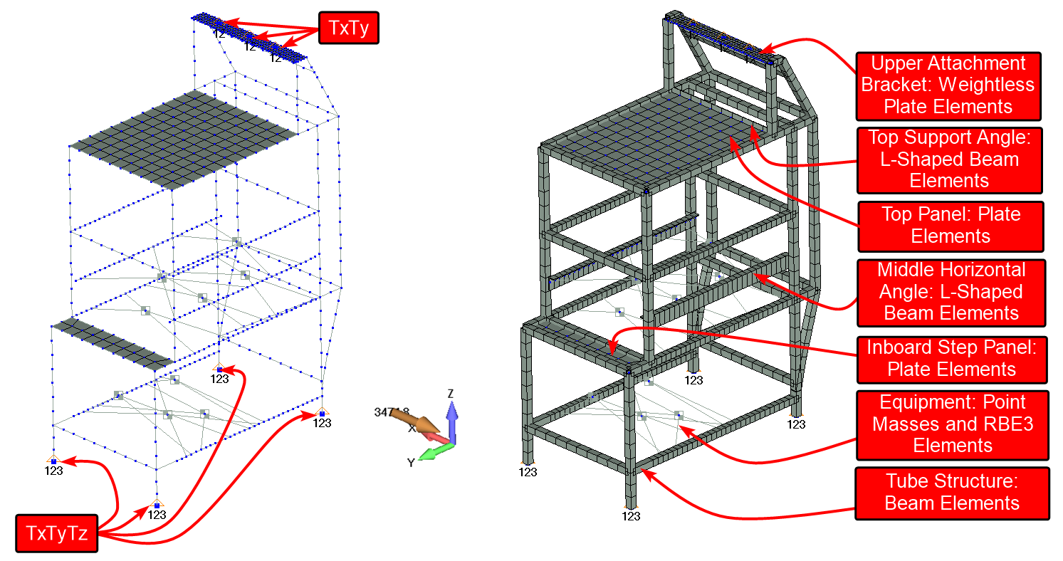
LOADS AND CONSTRAINTS
BOUNDARY CONDITIONSLower attachments
Tx, Ty, Tz restrained.
Upper attachmentsLateral and longitudinal translations restrained; vertical translation remains free.
Engineering rationale
The constraint set follows the attachment kinematics while avoiding unnecessary upper vertical fixity that would create an artificial load path and over-stiffen the rack.
Load application. FEMAP body loads are applied in the five governing directions (+z, −z, −y, +y and −x), allowing the distributed structural and payload masses to generate inertia consistently through the model.
ANALYSIS
SIMCENTER NASTRAN · SESTATIC / SOL 101
Linear static analysis is used because each certification load case is treated as a static inertial condition and the global rack response is evaluated within the source linear-strength framework.
Mass-based model with WTMASS
Mass is entered in lbm, density in lbm/in³ and acceleration in in/s². WTMASS provides consistent mass-to-force conversion so solver forces are recovered in lbf and stresses in psi.
Why WTMASS matters. In a non-coherent inch–lbm unit system, explicit mass conversion is required to avoid scaling errors between inertial input and recovered force. The parameter keeps the model’s mass definition consistent with engineering force output.
FEA RESULTS
Tube Structure
Weld stress treatment. Global beam forces are first converted to stresses in the 1 × 1 × 0.125 in tube. The same force resultants are then transferred to the weld section using its effective area and section-modulus relationships, so the local weld demand is evaluated against the reduced welded-material allowables rather than the parent-tube allowables.
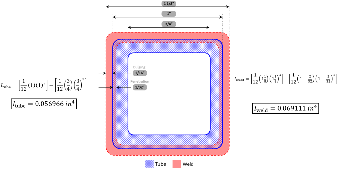
For a given bending moment (), the ratio of weld bending stress () to the tube bending stress () can be calculated as follows:
Hence, the weld bending stress () can be expressed as follows:
For a given axial load (), the ratio of weld axial stress () to the tube axial stress () can be calculated as follows:
Hence, the weld axial stress () can be expressed as follows:
the corresponding figure illustrates the distribution of the Axial Force and Bending moment, within the tube structure. This figure highlights that the highest Tensile and Compression Axial Forces and Bending moment are , , and , respectively. It is noteworthy that these maximum loads occur due to the load from the 9g FWD case. This scenario represents a critical load condition that must be thoroughly evaluated to ensure the structural resilience and safety of the structure under extreme operational loads.
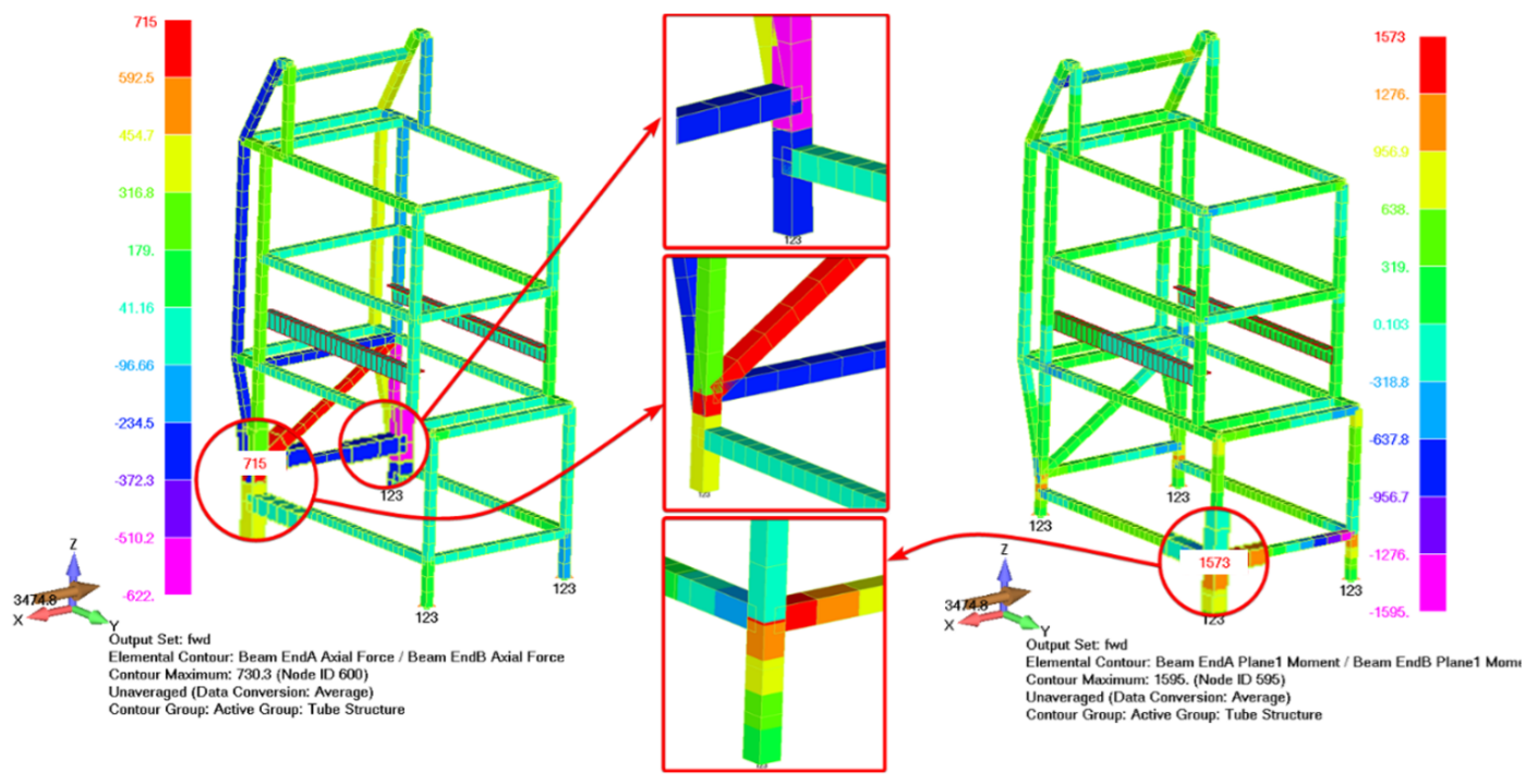
Based on the maximum Axial Force and Bending Moment values on the tube structure, the resulted axial and bending stresses at the tubes can be calculated as below:
Therefore, the maximum axial and bending stresses at the welds can be estimated as below:
Hence, the maximum tensile and compression stresses on the tubes and welds are as below:
The tube structure is fabricated from 1”x1”x0.125” aluminum extrusion, specifically using 6061-T6 alloy as per AMS-WW-T-700/6 TYPE II specifications. This material selection is noted for its high Ultimate Tensile Stress value of as documented in [MMPDS-15-Table 3.6.2.0(g)], and its Compression Yield Stress value is . Adjacent to the weld areas, Ultimate Tensile Stress and the Compression Yield Stress values are and , respectively, [Aluminum Design Manual 2010-Table 2-19W]. Since This reduction in strength accounts for the weakening effects of welding, which includes alterations in microstructure and potential introduction of stress concentrators. Therefore, the margin of safety in the Welded Tube Structure can be computed as below:
→ PASS
Column-Buckling allowable:
The column buckling allowable can be expressed as below:
Where, K is the buckling coefficient. Ec is the compressive modulus of elasticity of the material. I is the minimum moment of inertia of the column. L is the total length of column.
Since the tubes are welded and we are considering bending at the welds they are closer to fixed supports. A reasonable approximation would be to calculate the column allowable for the fixed-fixed case (K=4) as well as the pinned-pinned (K=1) case, then the average of the resulted critical values will be our benchmark.
The longest beam in the tube structure has a length of 35.7 in. Therefore, the critical buckling stresses can be calculated as below:
As previously shown, the maximum compression stress is and it occurs at the tubes. Therefore, the margin of safety in the Welded Tube Structure can be computed as below:
→ PASS
Structural Sheet Metals and their Attachments
In this section, the structural sheet metals will be assessed based on the maximum tensile and compressive principal stresses. The maximum tensile principal stress will be checked against the allowable ultimate tensile strength (ftu) of the material. On the other hand, the maximum compressive principal stress will be checked against the allowable yield compressive strength (fcy) of the material. The maximum principal stress (f1) and the minimum principal stress (f2) on both sides of the plates were reviewed for all cases, and it is summarized in the corresponding table.
Maximum and Minimum Principal Stresses for the Structural Sheet Metals within the Audio Equipment Rack. The cells highlighted in grey represent the maximum tensile and compressive principal stresses.
| Part Name | Plate Side | Stress Direction | FWD | UP | DOWN | INBOARD | OUTBOARD | MAX [ksi] |
MAX [ksi] |
|||||
|---|---|---|---|---|---|---|---|---|---|---|---|---|---|---|
f1 [ksi] |
f2 [ksi] |
f1 [ksi] |
f2 [ksi] |
f1 [ksi] |
f2 [ksi] |
f1 [ksi] |
f2 [ksi] |
f1 [ksi] |
f2 [ksi] |
|||||
Structural Sheet Metals 002-2302306-111 002-2302306-107 |
TOP | Tension | 1.31 | 0.28 | 1.31 | 0.38 | 1.05 | 0.75 | 0.11 | 0.03 | 0.09 | 0.04 | 1.43 | 1.43 |
| Compression | 0.28 | 1.34 | 0.69 | 0.96 | 0.42 | 1.43 | 0.04 | 0.09 | 0.03 | 0.11 | ||||
| BOT | Tension | 0.79 | 0.36 | 0.97 | 0.68 | 1.43 | 0.41 | 0.14 | 0.05 | 0.08 | 0.03 | |||
| Compression | 0.37 | 0.8 | 0.37 | 1.31 | 0.74 | 1.05 | 0.03 | 0.08 | 0.05 | 0.14 | ||||
As shown in the corresponding table and the corresponding figure, the Maximum Tensile Principal Stress for the Structural Sheet Metals reaches 6.02 ksi under the downward loading case at the bottom side of the plate. In addition, the Maximum Compressive Principal Stress reaches 6.03 ksi under the same loading case at the top side of the plates.
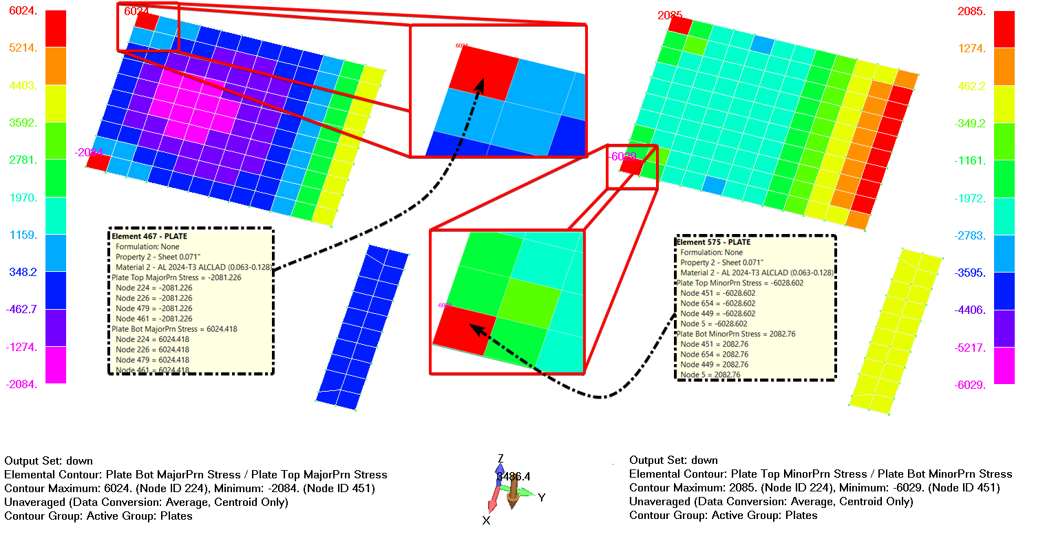
Based on the corresponding table, the structural sheet metals are made from 0.071” thick Aluminum 2024-T3 ALCLAD sheet. Based on the corresponding table, The allowable ultimate tensile strength (ftu) and allowable yield compressive strength (fcy) are 62 ksi and 37 ksi, respectively. The minimum margin of safety will be the lowest value between the tensile load MST and the compressive load MSC. These margins of safety can be expressed as below:
→ PASS
Loads on Rivets:
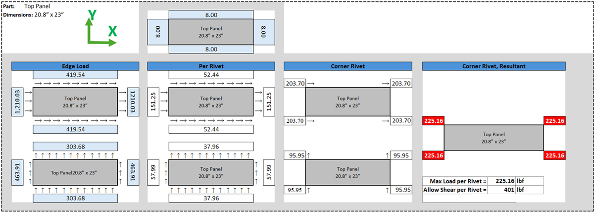
As shown in the corresponding figure. the Maximum Plate Membrane Forces per unit length in the structural sheet metals are as follows:
For the top panel: , , and .
For the inboard step panel: , , and
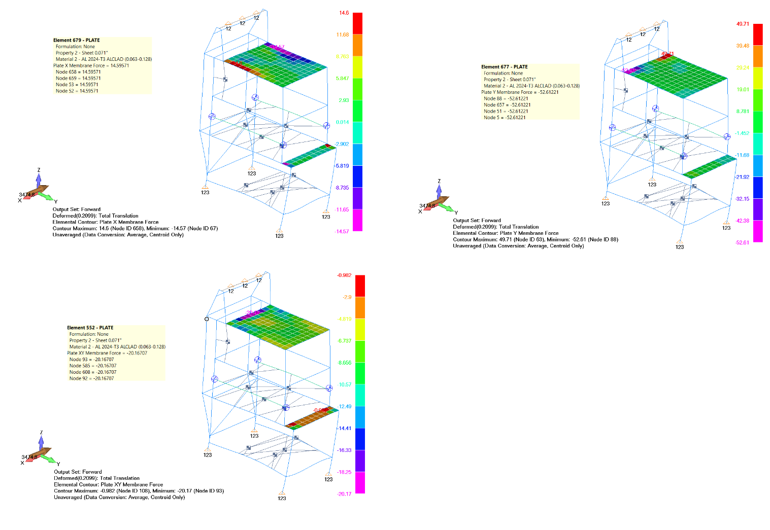
All these values belong to the forward load case. Conservatively, assume that these forces are equal along all the structural sheet metals edges, the maximum membrane forces at the longitudinal and lateral structural sheet metals edges, and for both the top (D: 20.8” x 23”) and inboard step (D: 20.8” x 4.8”) panels, can be calculated as below:
The top panel is fixed to tube structure using:
To the Tube Structure through 24 x CR3212 rivets along the lateral direction at the fwd and aft sides (12 on each side).
To the Tube Structure through 9 x CR3212 rivets along the longitudinal direction at the inboard side.
To the Top Support Angle through 8 x CR3212 rivets along the longitudinal direction at the outboard side.
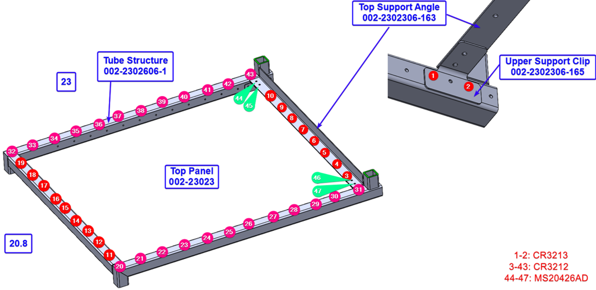
Top Panel attachment points
Conservatively, it is assumed that the load is carried through 8 rivets at each edge. Assuming that the load calculated previously will be evenly distributed between the 8 rivets at each edge, the load carried by each rivet will be as follows:
The rivet that is in the corner will carry the highest shear load because it carries loads due to Nx, Ny, Nxy, and Nyx. The total shear load carried by the corner rivet can be calculated as follows:
Based on the corresponding table, the CR3212 rivet has an ultimate shear load of 401 lbf. Therefore, the minimum margin of safety can be expressed as below:
→PASS
the corresponding figure illustrates the previous steps followed to calculate the minimum margin of safety of the Top Panel’s rivets.
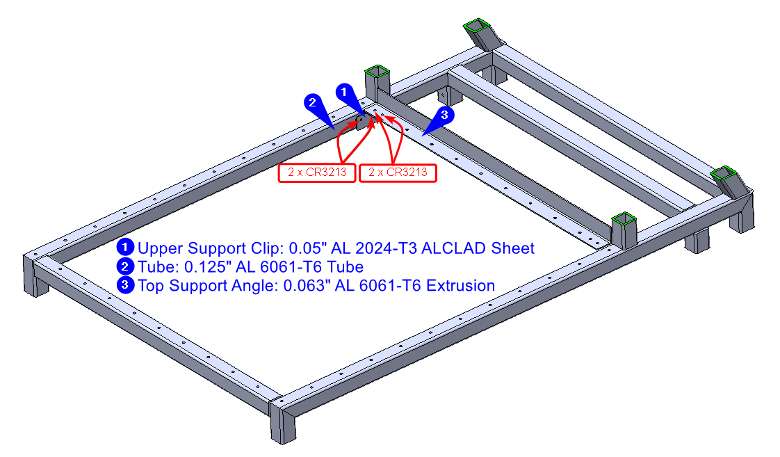
Top Support Angle and Upper Support Clips
As illustrated in the corresponding figure, the Upper Support Clip is made from 0.05” thick AL 2024-T3 ALCLAD Sheet. It is attached to the tube structure through two CR3213 rivets, and to the Top Support Angle though another two CR3213 rivets.
Based on the maximum Axial Force and Bending Moment values on the Top Support Angle (shown in the corresponding figure), the resulted axial and bending stresses can be calculated as below:
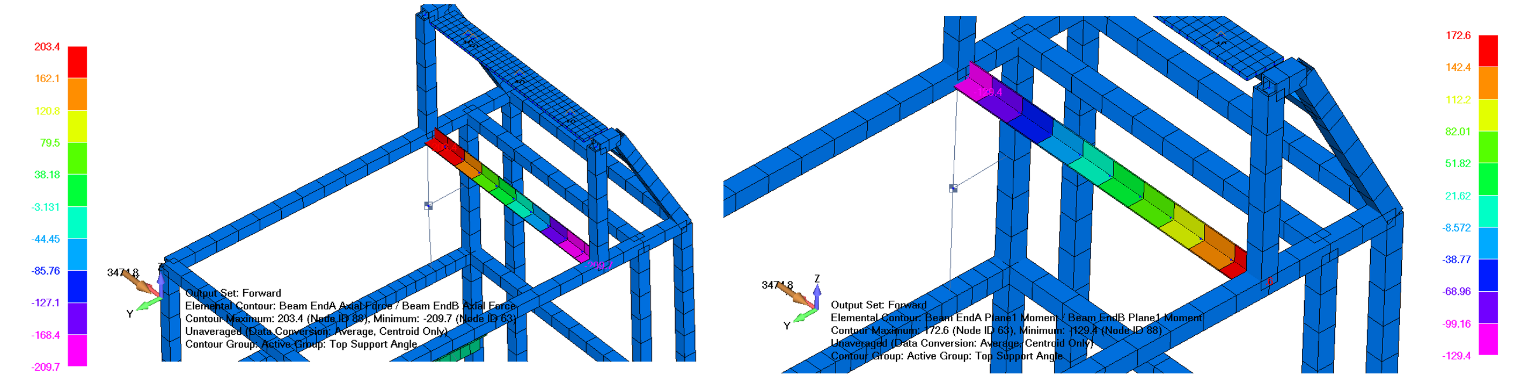
Therefore, the maximum tensile and compressive stresses on the Top Support Angle are as below:
The Top Support Angle is made from 0.063" AL 6061-T6 Extrusion. Based on the corresponding table, it has an Ultimate Tensile Strength value of , and a Compressive Yield Strength value is . Therefore, the margin of safety can be computed as below:
→ PASS
→ PASS
Column-Buckling allowable:
The column buckling allowable can be expressed as below:
Where, K is the buckling coefficient. Ec is the compressive modulus of elasticity of the material. I is the minimum moment of inertia of the column. L is the total length of column.
Since the Top Support Angle is attached to the Upper Support Clips though 4 rivets (2 at each side), this angle can be considered as pin-pin supported (K=1).
The Top Support Angle has a length of 18.9 in. Therefore, the critical buckling stresses can be calculated as below:
Therefore, the margin of safety in against buckling can be computed as below:
→ PASS
Mid Shelf Horizontal Angles
The two Mid Shelf Horizontal Angles are made from 0.125” thick AL 6061-T6 Extrusion. Each angle is attached to the tube structure through four CR3213 rivets (two at each side). Moreover, each angle is attached to two Vertical Support Angles that is made from the same material but 0.25” thick. This has been done through eight MS20470AD4 rivets (four for each Vertical Support Angle).
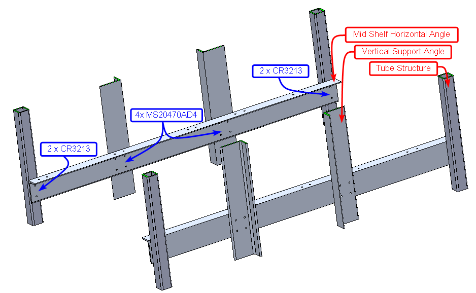
Based on the corresponding figures:
The maximum Tensile and Compressive Axial Forces in the Mid Shelf Horizontal Angle are 36.57 lbf and 39.89 lbf, respectively.
The maximum positive and negative bending moment values in plane 1 are 192.4 in- lbf and 209.8 in- lbf, respectively.
The maximum positive and negative bending moment values in plane 2 are 206 in- lbf and 214 in- lbf, respectively.
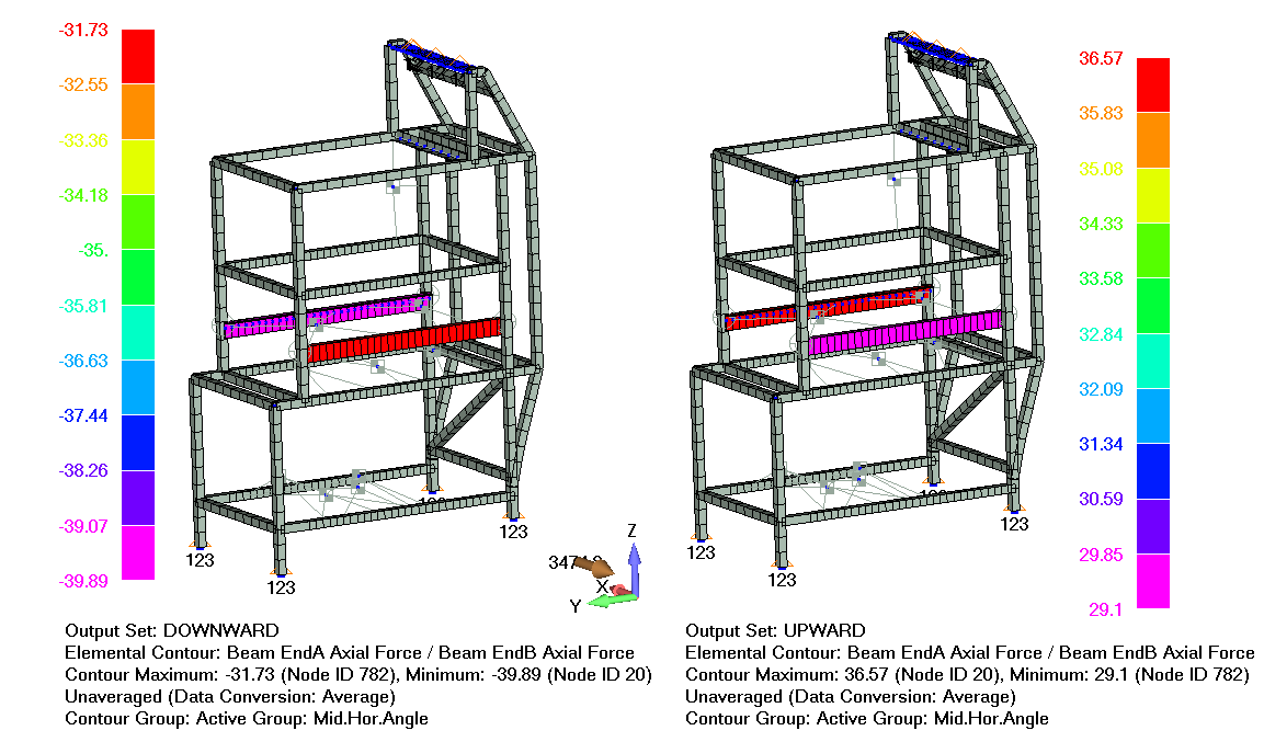
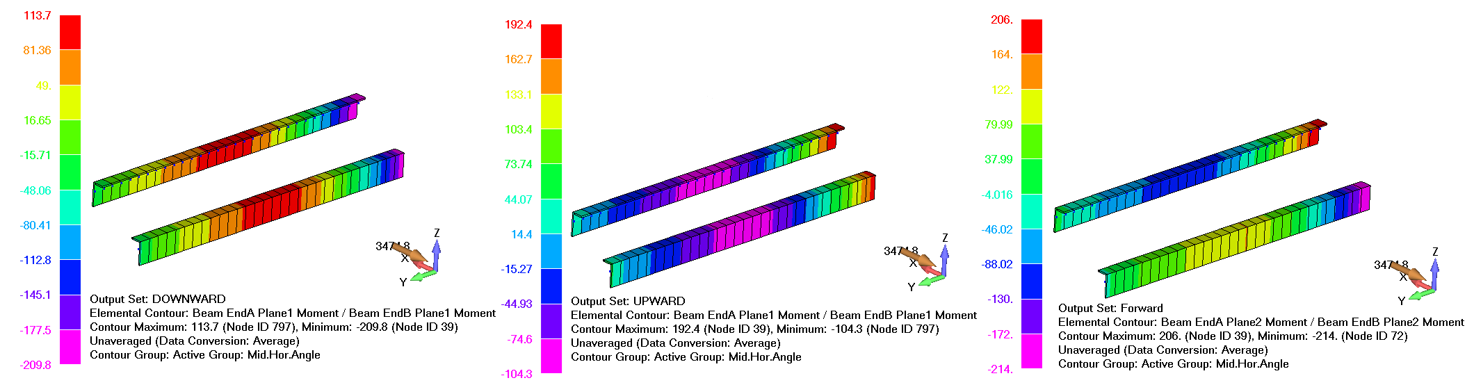
These maximum values belong to different loading cases scenarios and occur at different locations in the beams. Hence, by considering these values in calculating the maximum tensile and compressive combined stresses, the resulted value (calculated below) will be conservative.
The tensile and compressive bending stresses due to the maximum moments in plane 1 are:
Hence, the maximum tensile and compressive bending stresses due to the moment in plane 1 are:
AND
The tensile and compressive bending stresses due to the maximum moments in plane 2 are:
Hence, the maximum tensile and compressive bending stresses due to the moment in plane 2 are:
AND
The tensile and compressive axial stresses due to the maximum axial loads are:
Therefore, the maximum tensile and compressive combined stresses on the Mid Shelf Horizontal Angle are as below:
The Mid Shelf Horizontal Angle is made from 0.125" AL 6061-T6 Extrusion. Based on the corresponding table, it has an Ultimate Tensile Strength value of Ftu=38 ksi and a Compressive Yield Strength value of Fcy=34 ksi. Therefore, the margin of safety can be computed as below:
→ PASS
→ PASS
The Attachment Points
the corresponding table lists the reaction forces components carried by Upper and Lower studs in all cases. The highlighted cells represent the shear forces.
Reaction-force components (lbf) at the Upper and Lower attachment points for all cases. The highlighted cells represent the shear components.
| ID | Location | FORWARD | UP | DOWN | INBOARD | OUTBOARD | ||||||||||
|---|---|---|---|---|---|---|---|---|---|---|---|---|---|---|---|---|
| X | Y | Z | X | Y | Z | X | Y | Z | X | Y | Z | X | Y | Z | ||
| 1000001 | Upper FWD | 144.58 | 348.29 | 0 | 3.37 | -8.42 | 0 | -3.67 | 9.18 | 0 | -4.65 | -178.2 | 0 | 4.65 | 178.2 | 0 |
| 1000002 | Upper Mid | 68.46 | -54.06 | 0 | 0.13 | 9.76 | 0 | -0.14 | -10.64 | 0 | -0.38 | 174.96 | 0 | 0.38 | -174.96 | 0 |
| 1000003 | Upper AFT | 144.8 | -294.08 | 0 | -3.39 | -8.61 | 0 | 3.69 | 9.39 | 0 | 4.51 | -162.57 | 0 | -4.51 | 162.57 | 0 |
| 1000004 | Lower Inboard fwd | 237.31 | -0.42 | 170.65 | -1.76 | 72.47 | -300.57 | 1.92 | -79.04 | 327.79 | 0.43 | -24.81 | 8.28 | -0.43 | 24.81 | -8.28 |
| 1000005 | Lower Inboard aft | 237.1 | -0.92 | -170.28 | 1.48 | 85.91 | -346.62 | -1.61 | -93.7 | 378.01 | 0.43 | -28.17 | 7.07 | -0.43 | 28.17 | -7.07 |
| 1000006 | Lower Outboard fwd | 292.58 | 92.41 | 327.84 | -3.25 | -68.87 | -329.61 | 3.54 | 75.11 | 359.46 | -0.44 | -125.94 | -6.72 | 0.44 | 125.94 | 6.72 |
| 1000007 | Lower Outboard aft | 334.05 | -91.21 | -328.21 | 3.42 | -82.24 | -365.39 | -3.73 | 89.69 | 398.48 | 0.11 | -141.58 | -8.63 | -0.11 | 141.58 | 8.63 |
The resultant shear forces carried by each stud are listed in the corresponding table, and it is calculated using .
Resultant shear forces (lbf)
| ID | Location | Forward | Up | Down | Inboard | Outboard |
|---|---|---|---|---|---|---|
| 132 | Upper FWD | 377.11 | 9.07 | 9.89 | 178.26 | 178.26 |
| 428 | Upper Mid | 87.23 | 9.76 | 10.64 | 174.96 | 174.96 |
| 386 | Upper AFT | 327.8 | 9.25 | 10.09 | 162.63 | 162.63 |
| MAX | 377.11 | 9.76 | 10.64 | 178.26 | 178.26 | |
| 1000004 | Lower Inboard fwd | 237.31 | 72.49 | 79.06 | 24.81 | 24.81 |
| 1000005 | Lower Inboard aft | 237.1 | 85.92 | 93.71 | 28.17 | 28.17 |
| 1000006 | Lower Outboard fwd | 306.83 | 68.95 | 75.19 | 125.94 | 125.94 |
| 1000007 | Lower Outboard aft | 346.28 | 82.31 | 89.77 | 141.58 | 141.58 |
| MAX | 346.28 | 85.92 | 93.71 | 141.58 | 141.58 | |
Upper and Lower Attachment Studs
Based on the corresponding table, the maximum shear force carried by the Upper Stud is 377.11 lbf, which belongs to the forward load case. Moreover, the maximum shear force carried by the Lower Attachment Studs is 347.28 lbf which belong to the forward load case. Based on the corresponding table, the upper attachment stud and the FE200744 seat track stud have ultimate load capacities of 481 lbf and 2,000 lbf, respectively. Therefore, the minimum margin of safety can be expressed as below:
→ PASS
→ PASS
Upper Seat Track Tooth
The maximum shear load carried by the upper stud is . Hence, the moment at the stud’s head caused by the shear force can be calculated as below:
At the tooth, the maximum reaction force at each tooth can be calculated as below:
Hence, the margin of safety can be calculated as below:
→ PASS
Seat Track Stud
The Seat Track Stud is made from 1” thick AL 2024-T351 Plate. According to the corresponding table, the highest load among lower attachment points passes through the AFT outboard Seat Track Stud. Due to complex geometry, substantiation of this part is based on the non-linear FEM simulation.
The non-linear stress-strain properties of the material are shown on the corresponding figure. The yield and ultimate tensile strengths are taken conservatively relative to data in [MMPDS-15-Table 3.2.4.0(b)]. Moreover, tripled ultimate load was applied as shown on the corresponding figure.
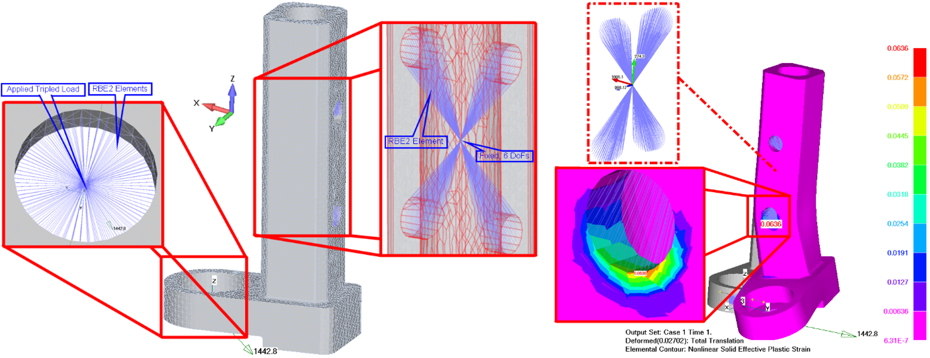
Tripled nonlinear-model loads
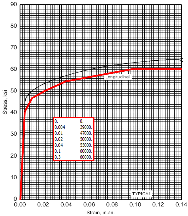
According to FEM results the highest strain is 0.0636in/in developing due to the triple load. Although this value is an artificial localized peak value due to its location near the RBE2 elements, considering this value will be conservative. According to the corresponding figure, the allowable strain is 0.14in/in. Therefore, the stud is capable to withstand the triple load and:
→ PASS
Two AN3-26A bolts are used to attach the stud to the tube structure.
Hence, based on the corresponding figure, the tensile and shear
loads carried be each bolt can be calculated as below:
Based on the corresponding table, the Ultimate Tensile and Shear Strength for the AN3-26 A are 2,210 lbf and 2,125 lbf, respectively. Hence, the fastener margin of safety can be calculated as below:
→ PASS
→ PASS
Equipment Installations
The equipment at the lowest part of the rack (which has the highest combined masses) are fixed on two beams that are fixed to the tube structure through CR3213 rivets. These equipment and their scaled-up masses are listed in the corresponding table. Since these equipment has the highest combined masses compared with the equipment at the other locations, only these equipment will be assessed to substantiate the equipment installation.
Equipment Installed at the Lowest Part of the Rack
| Equipment | Weight (lbf) |
Scaled Weight (lbf) |
Qty | Total Weight (lbf) |
|---|---|---|---|---|
| RT7000 Antenna Switching Unit | 0.35 | 0.525 | 2 | 1.05 |
| Remote Mount Tactical Radio LRU | 8.9(2) | 13.35 | 1 | 13.35 |
| RT7000 Mounting Tray | 1.6(3) | 2.4 | 1 | 2.4 |
| Artemis COMINT | 9.26 | 13.89 | 1 | 13.89 |
| Artemis COMINT T1001 Mounting Tray | 3.53 | 5.295 | 1 | 5.295 |
| HF Receiver/Exciter | 5.5 | 8.25 | 1 | 8.25 |
| KRX 1053 Tray | 0.4(4) | 0.6 | 1 | 0.6 |
| TOTAL | 44.84 | |||
HF Receiver/Exciter Group
As illustrated in the corresponding figure, the HF Receiver/Exciter is fixed to the KRX 1053 Tray that is fixed to the mounting tray via four AN525-832-8 screws. The mounting tray is fixed to the two Unequal Leg Extruded Angles through four MS24693-S273 screws, and the two Unequal Leg Extruded Angles are fixed to the tube structure through eight CR3213 rivets (four for each beam, two at each side)
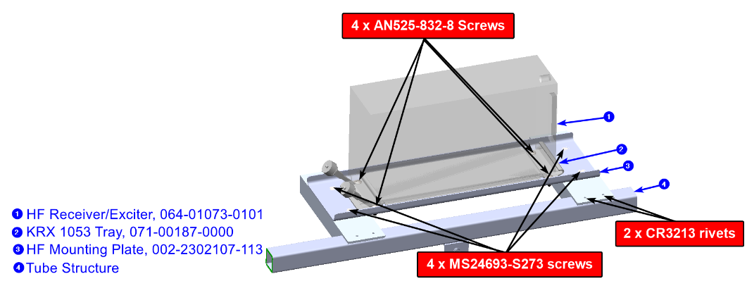
The mounting tray is 12.4654” long and 0.0625” thick, made from AL 2024-T3 CLAD Sheet, which has a density of 0.1 lbm/in3. Hence, the weight of this tray is 0.42 lbm. The weigh of the HF Receiver/Exciter and the KRX 1053 Tray are 8.25 lbm and 0.6 lbm, respectively. Hence, the total weight is 9.27 lbm (or 0.2881204 slug).
Beam idealization for equipment support. The mounting tray is treated as a simply supported beam. Depending on load direction, the equipment inertia is represented as a distributed or concentrated load, while the 2.866 in CoG offset is retained to capture the induced moment. This keeps the hand calculation conservative and traceable without relying on local tray contact details.
The FWD load can be calculated as below:
Forward inertial load acting along the negative x-axis:
The ultimate shear strength of the AN525-832-8 and MS24693-S273 Screws are 1,250 lbf and 1,020 lbf, respectively. Assuming that the FWD load (LFWD) is carried by only these screws, the screws pass by observation since their allowable shear loads are much higher than the applied FWD load.
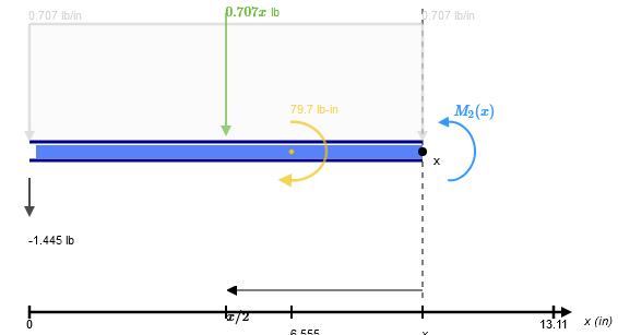
INBOARD CASE:
The combined weight of the equipment: W=1 x 32.174049 x 0.2881204 = 9.27 lbf
The INBOARD load’s moment: MINBOARD=3 x 32.174049 x 0.2881204 x 2.866 = +79.7 in-lbf
Rectangular Load Magnitude:
Rectangular Load Position:
Sum of forces along the y-axis is equal to zero for static equilibrium:
Sum of moments about the left support is equal to zero for static equilibrium:
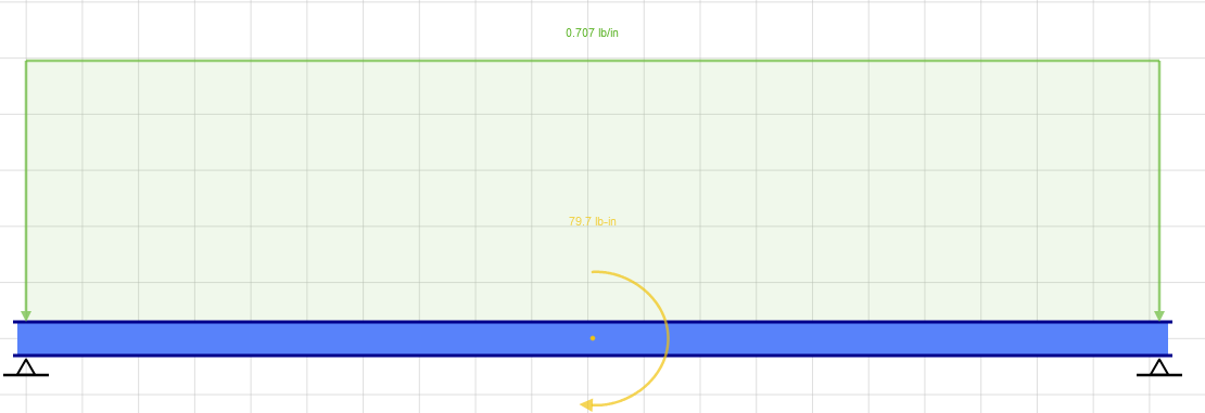
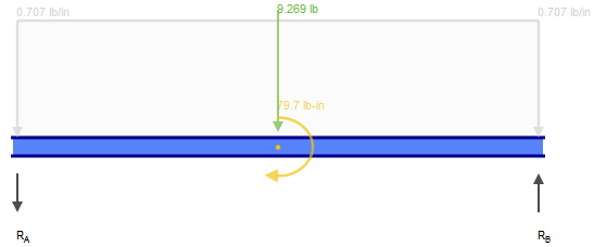
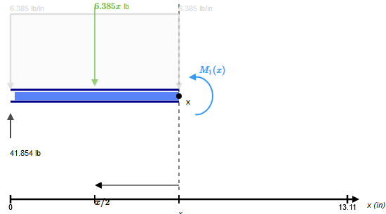
Take a cut for . The rectangular DL acts at distance of x/2 from the cut with a force of . Hence, the moment force is .
Therefore, the moments due to the DL can be calculated as below:
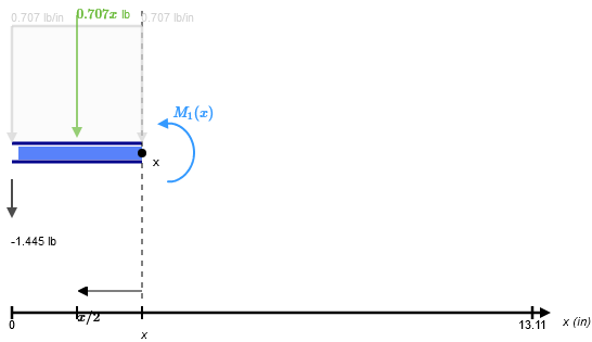
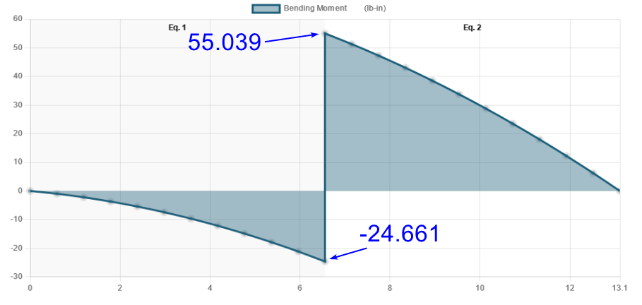
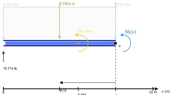
Take a cut for The rectangular DL acts at distance of x/2 from the cut with a force of . Hence, the moment force is .
Therefore, the moments due to the DL can be calculated as below:
OUTBOARD CASE:
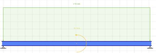
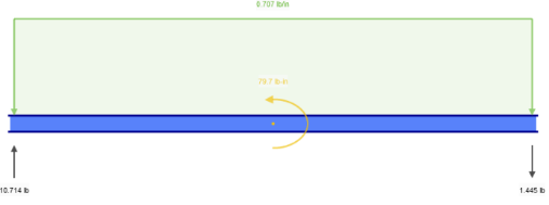
The combined weight of the equipment: W=1 x 32.174049 x 0.2881204 = 9.27 lbf
The OUTBOARD load’s moment: MOUTBOARD=3 x 32.174049 x 0.2881204 x 2.866 = -79.7 in-lbf around x-axis.
Rectangular Load Magnitude:
Rectangular Load Position:
Sum of forces along the y-axis is equal to zero for static equilibrium:
Sum of moments about the left support is equal to zero for static equilibrium:
Take a cut for . The rectangular DL acts at distance of x/2 from the cut with a force of . Hence, the moment force is .
Therefore, the moments due to the DL can be calculated as below:
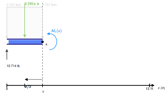
Take a cut for . The rectangular DL acts at distance of x/2 from the cut with a force of . Hence, the moment force is .
Therefore, the moments due to the DL can be calculated as below:
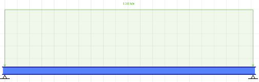
Downward case:
The DOWNWARD load: LDOWNWARD=9.03 x 32.174049 x 0.2881204 = 83.71 lbf
Rectangular Load Magnitude:
Rectangular Load Position:
Sum of forces along the y-axis is equal to zero for static equilibrium:
Sum of moments about the left support is equal to zero for static equilibrium:
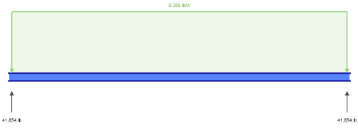
Take a cut for . The rectangular DL acts at distance of x/2 from the cut with a force of . Hence, the moment force is .
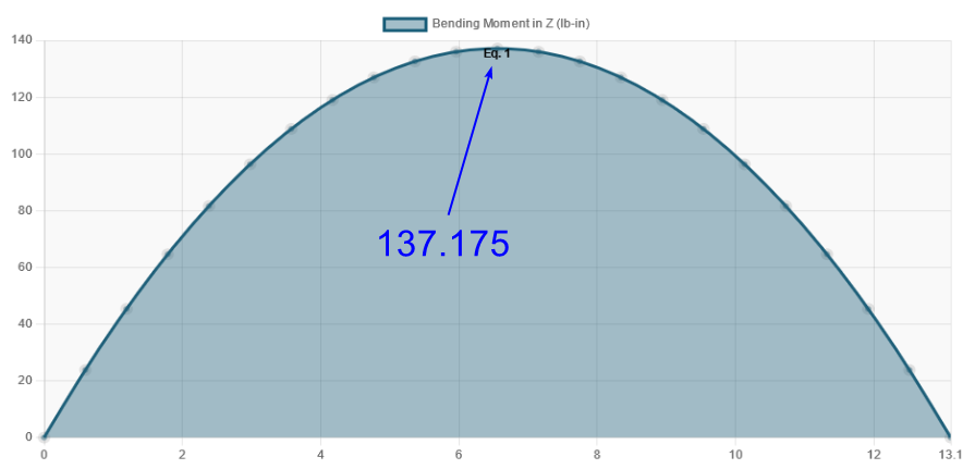
Therefore, the moments due to the DL can be calculated as below:
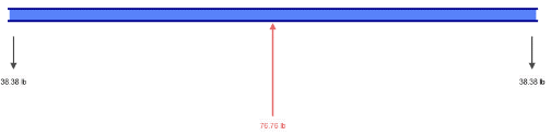
Upward case:
The UPWARD load: LUPWARD=8.28 x 32.174049 x 0.2881204 = 76.76 lbf
Sum of forces along the y-axis is equal to zero for static equilibrium:
Sum of moments about the left support is equal to zero for static equilibrium:
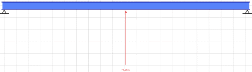
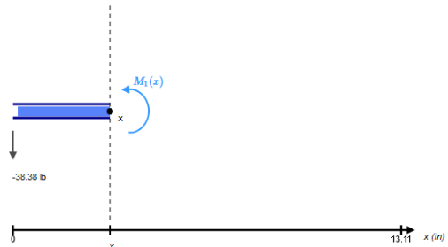
Take a cut for .
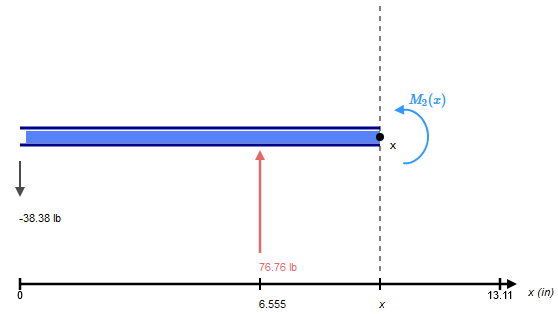
Take a cut for .
FWD case:
The combined weight of the equipment: W=1 x 32.174049 x 0.2881204 = 9.27 lbf along negative z-axis
The FWD load’s moment: MFWD=9 x 32.174049 x 0.2881204 x 2.866 = -239.11 in-lbf around y-axis.
→
The maximum bending moments in the beam material can be computed as below:
→
→
The developed maximum reaction forces and moments.
Ra (lbf) |
Rb (lbf) |
(in-lbf) |
(in-lbf) |
||
|---|---|---|---|---|---|
| MAX +M | MAX -M | - | |||
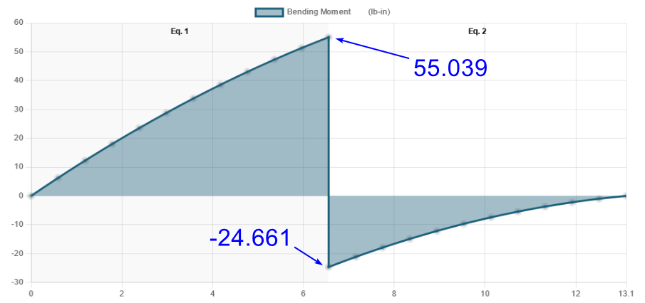
| Inboard | -1.445 | 10.714 | 55.039 | -24.661 | - |
| Outboard | 10.714 | -1.445 | 55.039 | -24.661 | - |
| Downward | 41.854 | 41.854 | 137.175 | - | - |
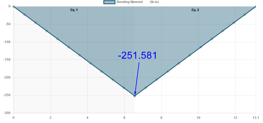
| Upward | 38.38 | 38.38 | - | -251.581 | - |
| Forward | 108.6 | 108.6 | 15.19 | - | 239.11 |
Based on the corresponding table, the maximum value of reaction force belongs to the 9g FWD case, where the reaction forces equal 108.6 lbf. The ultimate tensile strength of the AN525-832-8 and MS24693-S273 Screws are 1,525 lbf and 1,200 lbf, respectively. Assuming that the reaction forces are carried by only these screws, the screws pass by observation since their allowable tensile loads are much higher than the resulted reaction forces.
The maximum positive and negative bending moments in the YZ plane are 137.18 in-lbf and 251.58 in-lbf, respectively. These values belong to the downward and upward cases, respectively. These bending moments result in the below maximum tensile and compressive bending stresses:
Therefore, the maximum tensile and compressive bending stresses in the YZ plane are 33.85 ksi and 18.46 ksi, respectively. The ultimate tensile strength and yield compressive strength of the AL 2024-T3 CLAD Sheet are 60 lbf and 36 lbf, respectively. Therefore, the margin of safety for the mounting tray can be expressed as below:
→ PASS
→ PASS
The maximum positive and negative bending moments in the XZ plane are 239.11 in-lbf. These values belong to the forward case. These bending moments result in the below maximum tensile and compressive bending stresses:
The ultimate tensile strength and yield compressive strength of the AL 2024-T3 CLAD Sheet are 60 lbf and 36 lbf, respectively. Therefore, the margin of safety for the 002-2302107-113 mounting tray can be expressed as below:
→ PASS
→ PASS
Artemis COMINT Group
As illustrated in the corresponding figure, Artemis COMINT is fixed to the Artemis COMINT Mounting Tray and the two Unequal Leg Extruded Angles through four MS24693-S273 screws.
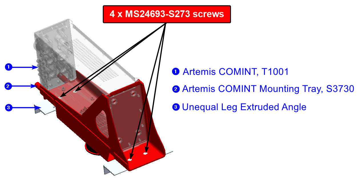
The weigh of the Artemis COMINT and the Artemis COMINT Mounting Tray are 13.89 lbm and 5.3 lbm, respectively. Hence, the total weight is 19.19 lbm (or 0.59644343 slug). In order to estimate the reaction force at the MS24693-S273 screws, the 3D Rigid Body Analysis was used.
Developed Reaction Forces at the MS24693-S273 Screws
| Forward | Inboard | Outboard | Upward | Downward | ||||||||||||||||
|---|---|---|---|---|---|---|---|---|---|---|---|---|---|---|---|---|---|---|---|---|
| Rx | Ry | Rs | Rz | Rx | Ry | Rs | Rz | Rx | Ry | Rs | Rz | Rx | Ry | Rs | Rz | Rx | Ry | Rs | Rz | |
| INBOARD, FWD | 24.9 | 0.5 | 24.9 | 45.9 | -0.1 | -7.0 | 7.0 | 2.0 | 0.1 | 7.0 | 7.0 | -2.0 | 0.0 | 0.0 | 0.0 | -24.2 | 0.0 | 0.0 | 0.0 | 26.3 |
| INBOARD, AFT | 24.9 | -0.5 | 24.9 | -45.9 | -0.1 | -7.0 | 7.0 | 2.0 | 0.1 | 7.0 | 7.0 | -2.0 | 0.0 | 0.0 | 0.0 | -21.8 | 0.0 | 0.0 | 0.0 | 23.8 |
| OUTBOARD, FWD | 17.1 | 0.5 | 17.1 | 45.9 | 0.1 | -7.0 | 7.0 | -2.0 | -0.1 | 7.0 | 7.0 | 2.0 | 0.0 | 0.0 | 0.0 | -16.8 | 0.0 | 0.0 | 0.0 | 18.3 |
| OUTBOARD, AFT | 17.1 | -0.5 | 17.1 | -45.9 | 0.1 | -7.0 | 7.0 | -2.0 | -0.1 | 7.0 | 7.0 | 2.0 | 0.0 | 0.0 | 0.0 | -14.5 | 0.0 | 0.0 | 0.0 | 15.8 |
| MAX | 24.9 | 0.5 | 24.9 | 45.9 | 0.1 | -7.0 | 7.0 | 2.0 | 0.1 | 7.0 | 7.0 | 2.0 | 0.0 | 0.0 | 0.0 | -14.5 | 0.0 | 0.0 | 0.0 | 26.3 |
As listed in the corresponding table, the maximum shear and tensile load carried by the MS24693-S273 screw are 24.9 lbf and 45.9 lbf, respectively. These values belong to the forward load case.
The ultimate shear and tensile strengths for the MS24693-S273 screws are 1,020 lbf and 1,200 lbf, respectively. Therefore, these screws pass by observation since their allowable shear and tensile loads are much higher than the resulted reaction forces.
Substantiation Outcome
Heavier common configuration used to envelope the Power Rack.
Tube/weld strength, buckling and sheet-metal checks satisfy the source assessment.
Upper/lower studs, seat-track tooth and critical fasteners are substantiated by calculation or conservative comparison.
Critical lower-rack equipment groups are checked using reaction, beam and fastener substantiation.
Structural substantiation complete
The evaluated rack structure, attachment load paths and selected governing equipment installations satisfy the source report’s strength criteria for the assessed load cases.
REFERENCES
Structural Methods & Allowables
- MMPDS-15 - Metallic Materials Properties Development and Standardization
- Analysis & Design of Flight Vehicle Structures - E. F. Bruhn
- Aluminum Design Manual 2010
Regulatory & Aircraft Load Basis
- Federal Aviation Regulations - 14 CFR Part 25
- DHC-8-100 Load Cases and Applied Loads
Fasteners & Hardware Data
- NAS528 Fastener Codes
- CHERRYMAX Rivets technical data
- MS24693 technical data
- MS35206 technical data
- NAS1801 technical data
- NASM525 technical data
- NAS8602 technical data
- NASM3-20 technical data
Track & Stud Data
- FE200744 stud technical data
- ANCRA Clear Medium-Duty Aircraft Track - 40456-10-144 technical data
- ANCRA Threaded Stud - 40351 / 40352 technical data
- Installed-equipment manufacturer specification sheets cited in the source report