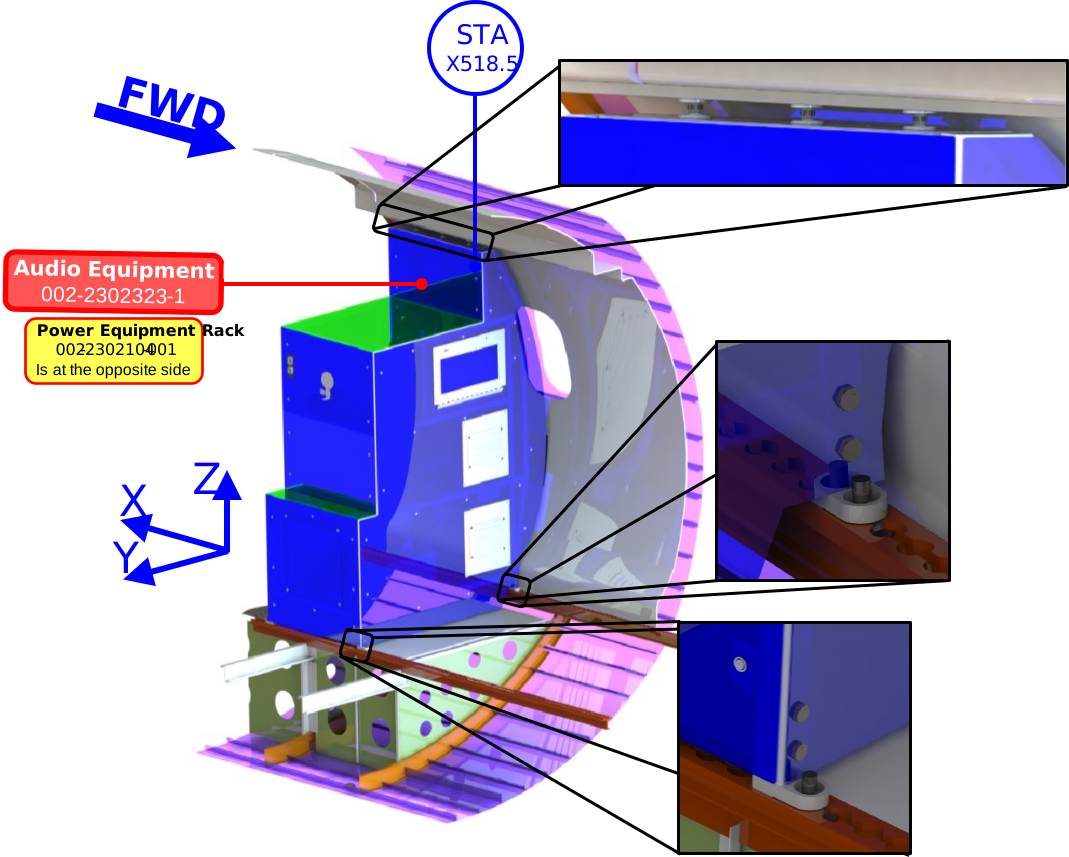
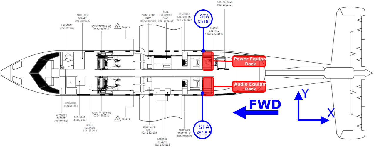
Located at X518.5 and carrying the larger installed equipment mass.
INTRODUCTION
AircraftDHC-8-100Interior equipment-rack modification
InstallationsAudio · Port / Power · StarboardCommon structural architecture at X518.5
Governing configurationAudio Equipment RackHeavier installation; Power Rack covered by comparison
Substantiation routeFEA + classical checksJoints, beams, plates, attachments and equipment support
Structural substantiation of the port Audio Equipment Rack and starboard Power Equipment Rack on a DHC-8-100. The assessment traces equipment inertia through the rack frame, panels, local support angles and aircraft attachments, then verifies the governing members, joints and equipment supports using FEMAP/NASTRAN and classical aerospace stress methods.
DESIGN ASSESSMENT
Governing Configuration & Load Path
Same rack architecture and station; lower payload than the Audio rack.
The two installations share the same structural design and fuselage station, so the heavier rack envelopes the common structural response.
The Power Rack is substantiated by comparison to the heavier Audio Rack rather than duplicating an equivalent FE assessment.
Governing-model decision
The Audio Equipment Rack is selected for detailed substantiation because its higher installed mass produces the conservative inertial demand for two otherwise equivalent rack structures.
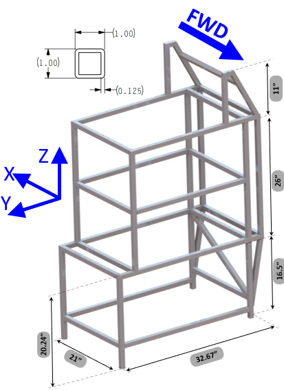
I used the heavier Audio Equipment Rack as the governing global model because both racks share the same structural architecture and installation station, while the Audio rack carries the larger equipment mass. Equipment inertia is introduced into the tube frame through RBE3-connected point masses so the payload is transferred without adding artificial stiffness. Removed panels, small hardware, and other non-structural items are recovered as distributed non-structural mass on the tube structure. The global load path therefore runs from equipment and distributed mass into the rack frame, then through the upper and lower stud attachments into the aircraft structure. The upper attachment bracket is assessed in a separate local FE model because its detailed geometry and local stress question require more resolution than the global rack model.
The Audio and Power racks share the same structural architecture and fuselage station. The Audio Rack is the heavier installation, so it is used as the governing global model and envelopes the Power Rack for the common structural response.
Materials, Joint Basis & Mass Representation
The primary rack structure uses AL 6061-T6 tube/extrusions with AL 2024-T3 CLAD sheet components. Fastener allowables are established for the actual installed sheet stack: the usable joint value is the lowest applicable shear, countersunk-joint or bearing capacity rather than the isolated catalog fastener strength. Unverified equipment weights retain the source 1.5 scaling assumption.
Joint allowable philosophy
Use the weakest applicable failure path for the actual fastener / sheet stack-not the isolated fastener strength.
Sheet thickness and material can govern joint strength.Countersunk geometry is checked with the applicable static-joint reduction.Rivet tension is checked only when a meaningful tensile reaction exists.
Representative governing joint allowables retained from the source assessment.
| Fastener / fitting | Tension allowable [lbf] | Shear / local allowable [lbf] | Engineering use |
|---|---|---|---|
| MS20426AD4 | — | 259 | CSK solid-rivet joints |
| MS20470AD4 | — | 375 | Protruding-head rivet joints |
| CR3212 | 285 | 401 | Top-panel / sheet attachments |
| CR3213 | 285 | 422 | Rack-frame attachments |
| MS24693-S273 | 1,200 | 1,020 | Equipment mounting |
| Upper attachment stud | 4,000 | 481 | Upper aircraft attachment |
| FE200744 | 5,000 | 2,000 | Lower seat-track stud |
| Track tooth | 2,250 | — | Seat-track local reaction |
3D-model-derived weight and CoG
Modeled rack parts use the source aluminum density assumption and retain their 3D-model center-of-gravity locations.
Vendor mass + installation allowance
Equipment weights come from specification data and are scaled by 1.5 where specified to include attachment hardware and wiring/cabling.
Tube structure: 33.64 lbf
Equipment units: 79.52 lbf
Riveted panels: 4.083 lbf
Non-structural assembly: 22.913 lbf
Removable panels: 17.918 lbf
Total rack representation: 158.074 lbf
Mass-modeling decision. Structural mass is represented directly from modeled geometry, while omitted panels, small hardware and installed equipment are recovered as non-structural or concentrated mass so inertia is retained without artificially stiffening the rack.
STATIC STRESS ANALYSIS
Load Cases Formulation
REGULATORY SOURCE BASISFAR Part 25 criteria used to formulate the structural load envelope
Flight-load framework
FAR 25.321 and 25.331–25.351
- General flight loads and symmetric maneuver response
- Flight maneuver envelope and design airspeeds
- Limit maneuver factors, gust and turbulence loads
- Fuel/oil, high-lift, rolling and yaw conditions
Emergency landing
FAR 25.561
- Forward: 9 g
- Downward: 6 g
- Upward: 3 g
- Sideward: 3 g airframe / 4 g seats & attachments
- Rearward: 1.5 g
Governing ultimate load cases.
Load Case Number |
Load Factor Direction |
Ultimate Load Value () [g] |
Governing basis |
|---|---|---|---|
| 1 | Up | 8.28 | Flight |
| 2 | Down | 9.03 | Flight |
| 3 | Outboard | 3.0 | Emergency landing |
| 4 | Inboard | 3.0 | Emergency landing |
| 5 | Forward | 9.0 | Emergency landing |
| Not required | Aft | 1.5✝ | Covered conservatively by Forward case |
| ✝ This case is covered by the 9G Forward case, so it will not be required. | |||
I compared the applicable flight and emergency-landing demands direction by direction and retained only the governing condition. Flight loading governs the vertical directions at the rack station, giving 8.28 g upward and 9.03 g downward ultimate acceleration. FAR 25.561 emergency-landing loading governs the 3.0 g outboard, 3.0 g inboard, and 9.0 g forward directions. The 1.5 g aft condition is not modeled separately because it is conservatively enveloped by the 9.0 g forward case. This produces five traceable certification load cases without duplicating non-governing conditions.
Finite Element Analysis (FEA)
Audio Rack envelopes the Power Rack
Both racks use the same structural design at the same fuselage station. The Audio Rack is approximately 45 lbf heavier, so its inertial response is used to substantiate the common rack architecture.
Model & Idealization
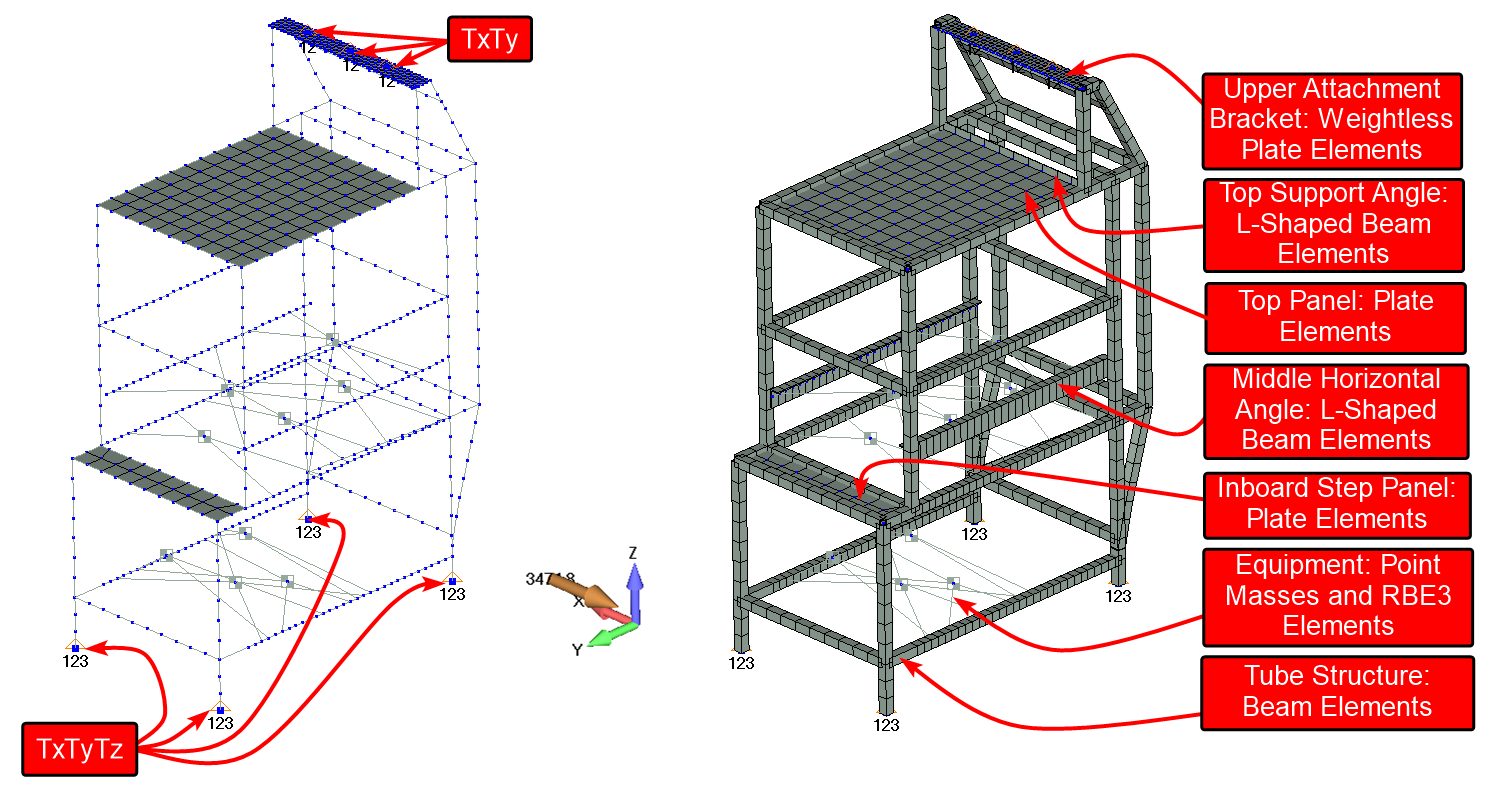
Square tube structure
The welded square-tube frame is modeled with beam elements so section area, inertia, axial force, shear and bending are recovered efficiently along the primary load path.
Top + inboard step panels
Thin sheet components are modeled with plate elements to retain membrane and bending stiffness efficiently.
Support and shelf angles
L-shaped beam properties preserve the angle section stiffness and principal load path without unnecessary solid geometry.
Upper attachment bracket
The global rack model uses a weightless plate representation for load transfer, while the actual bracket assembly is evaluated in a dedicated local model where local stresses matter.
Point masses + RBE3
Equipment inertia is transferred to the rack without adding artificial stiffness-appropriate when payload stiffness is not credited structurally.
Non-critical holes covered
Holes that do not control the primary load path are suppressed to avoid artificial mesh-driven stress peaks and reduce model complexity.
Loads & Constraints
BOUNDARY CONDITIONSLower attachments
Tx, Ty, Tz restrained.
Upper attachmentsLateral and longitudinal translations restrained; vertical translation remains free.
Engineering rationale
The constraint set follows the attachment kinematics while avoiding unnecessary upper vertical fixity that would create an artificial load path and over-stiffen the rack.
Load application. FEMAP body loads are applied in the five governing directions (+z, −z, −y, +y and −x), allowing the distributed structural and payload masses to generate inertia consistently through the model.
Analysis
SIMCENTER NASTRAN · SESTATIC / SOL 101
Linear static analysis is used because each certification load case is treated as a static inertial condition and the global rack response is evaluated within the source linear-strength framework.
Mass-based model with WTMASS
Mass is entered in lbm, density in lbm/in³ and acceleration in in/s². WTMASS provides consistent mass-to-force conversion so solver forces are recovered in lbf and stresses in psi.
Why WTMASS matters. In a non-coherent inch–lbm unit system, explicit mass conversion is required to avoid scaling errors between inertial input and recovered force. The parameter keeps the model’s mass definition consistent with engineering force output.
Governing Results
Governing combined compression at the reduced welded-material allowable.
Governing aircraft-attachment shear check including the source fitting factor.
Corner rivet from conservative membrane-force distribution.
Nonlinear strain-based check using the source tripled-load assessment.
Primary Frame, Weld Strength & Buckling
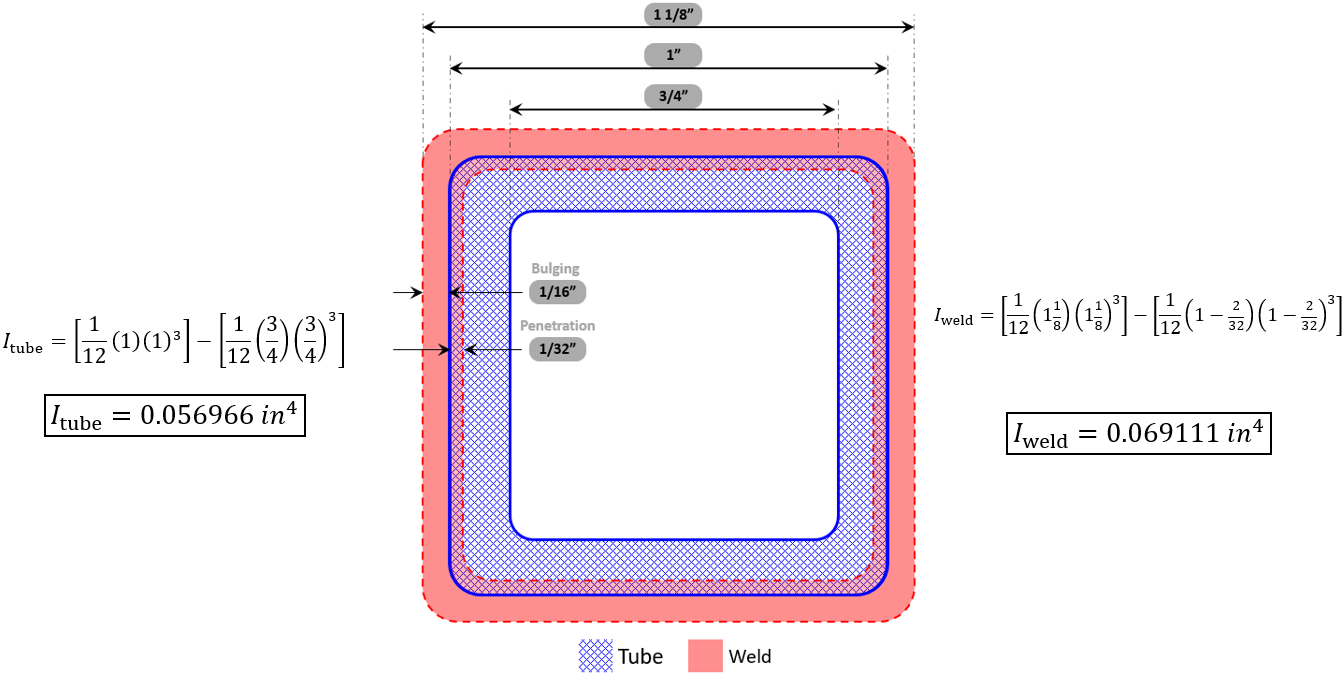
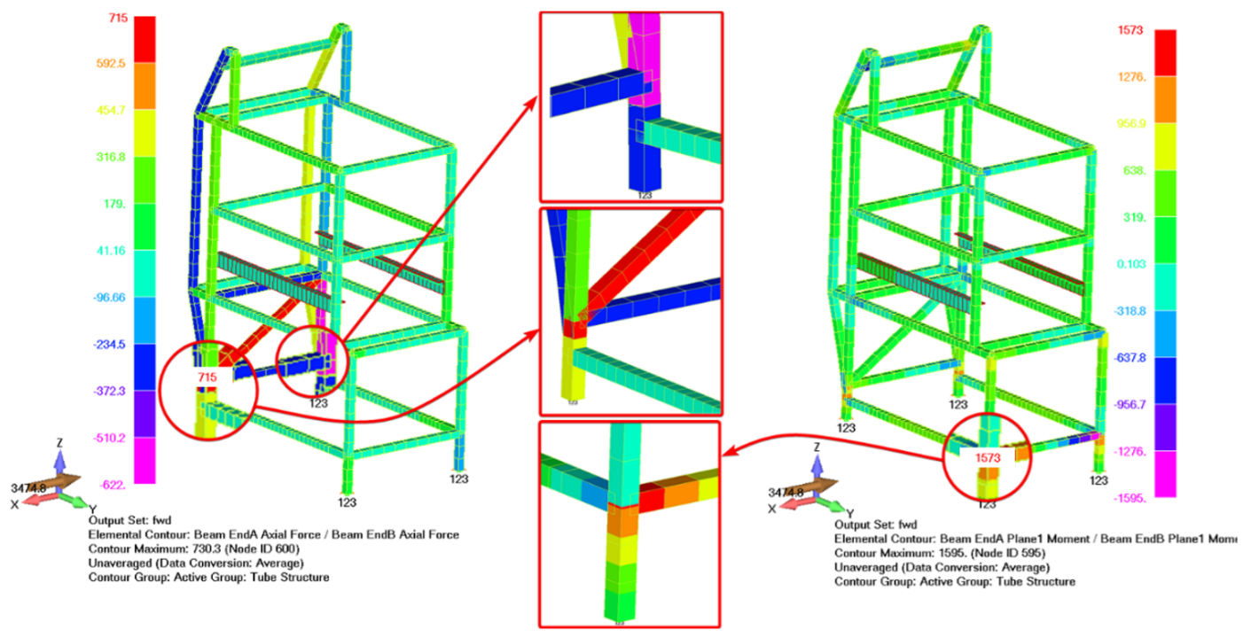
The 1 × 1 × 0.125 in AL 6061-T6 square-tube frame is assessed from recovered beam axial force and bending moment. The 9 g forward case governs with approximately 715.7 lbf tension, 622.5 lbf compression and 1,573 in-lbf bending moment. Local weld stresses are obtained from the tube force resultants using the source weld-section area and section-modulus relationships, then checked against reduced welded-material allowables.
→ PASS
Column stability is also checked for the longest 35.7 in tube member. The source assessment brackets the end condition using pin-pin and fixed-fixed Euler solutions and uses the average critical stress, 25.45 ksi, as the benchmark.
→ PASS
Panels, Principal Stress & Riveted Load Transfer
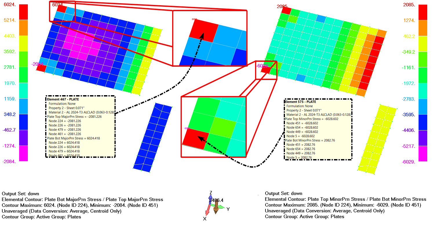
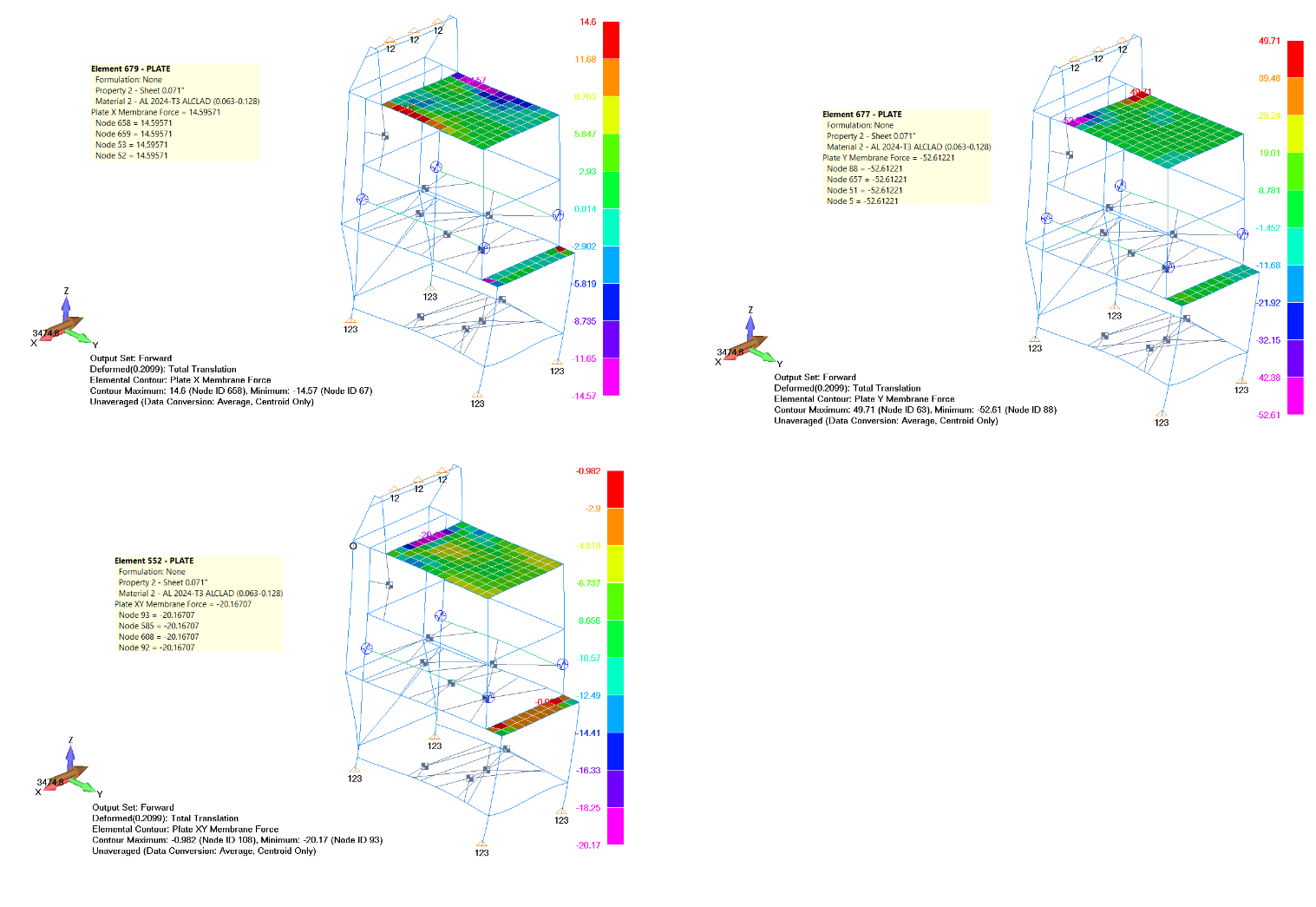
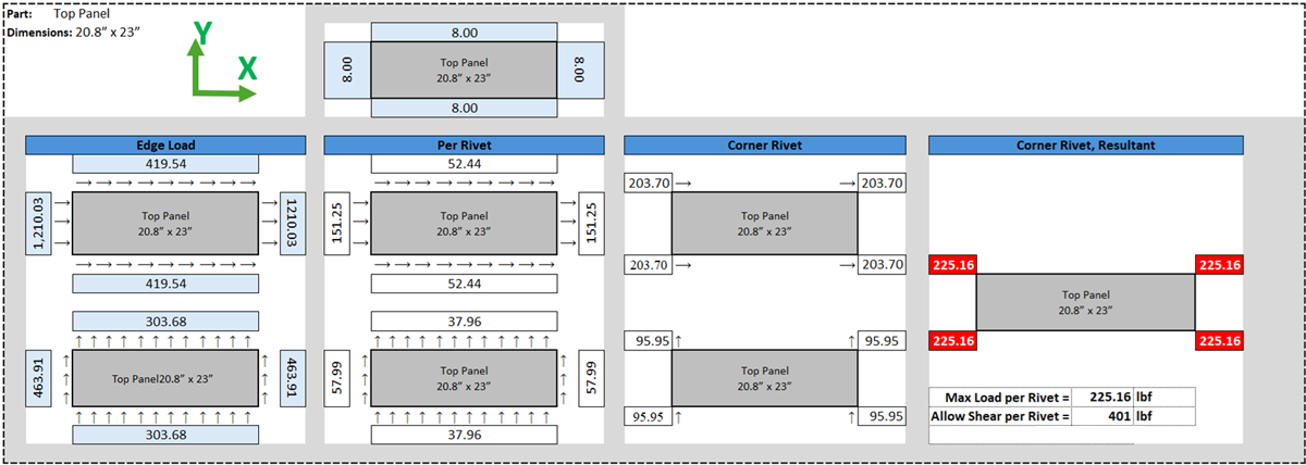
Plate results are screened using maximum tensile and compressive principal stress on both faces. The sheet-metal stress check has substantial reserve; the more informative local check is the transfer of membrane forces into the top-panel rivet pattern. For the forward case, the retained membrane resultants are Nxy = 20.17 lb/in, Nx = 14.6 lb/in and Ny = 52.61 lb/in on the top panel. A conservative eight-rivet-per-edge distribution places the corner CR3212 rivet at 225.16 lbf shear.
→ PASS
→PASS
Local Angle Strength & Stability
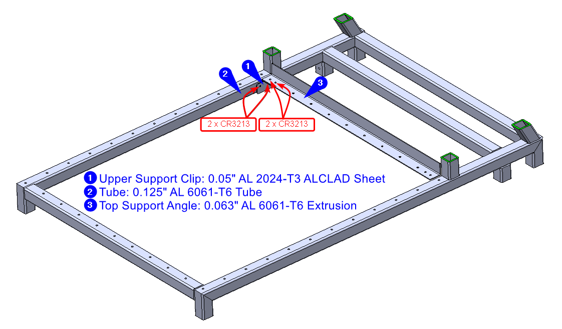
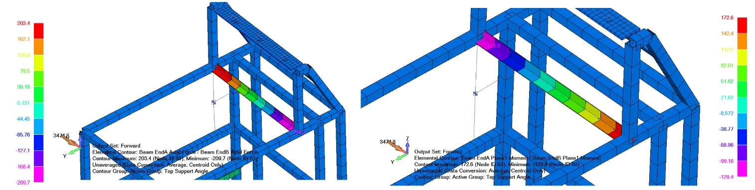
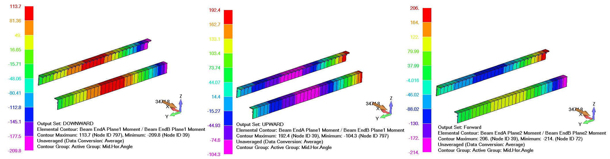
The top support angle and mid-shelf angles are retained as beam sections so axial force and two-plane bending can be recovered directly. The top support angle reaches 15.68 ksi compression and 2.14 ksi tension; the corresponding compression-strength and pin-pin buckling checks both pass. For the mid-shelf angle, conservative combination of maxima from different locations/load cases gives approximately 7.89 ksi tension and 8.29 ksi compression, both well below the AL 6061-T6 allowables.
→ PASS
→ PASS
→ PASS
→ PASS
→ PASS
Aircraft Attachments & Seat-Track Substantiation
The attachment reactions are recovered from the global FEM and reduced to local stud demand. The upper attachment is governing: the source calculation uses 377.11 lbf maximum shear from the forward case against a 481 lbf stud-bending/shear allowable with a 1.15 fitting factor.
→ PASS
→ PASS
The same upper-stud load produces a 607.15 in-lbf local moment and a 1,598 lbf reaction at the track tooth, checked against the 2,250 lbf per-tooth allowable.
→ PASS
The lower seat-track stud is assessed with a dedicated nonlinear material model using AL 2024-T351 stress-strain data. The governing source load vector is tripled for the local model; the recovered peak strain is 0.0636 in/in against a 0.14 in/in allowable strain.
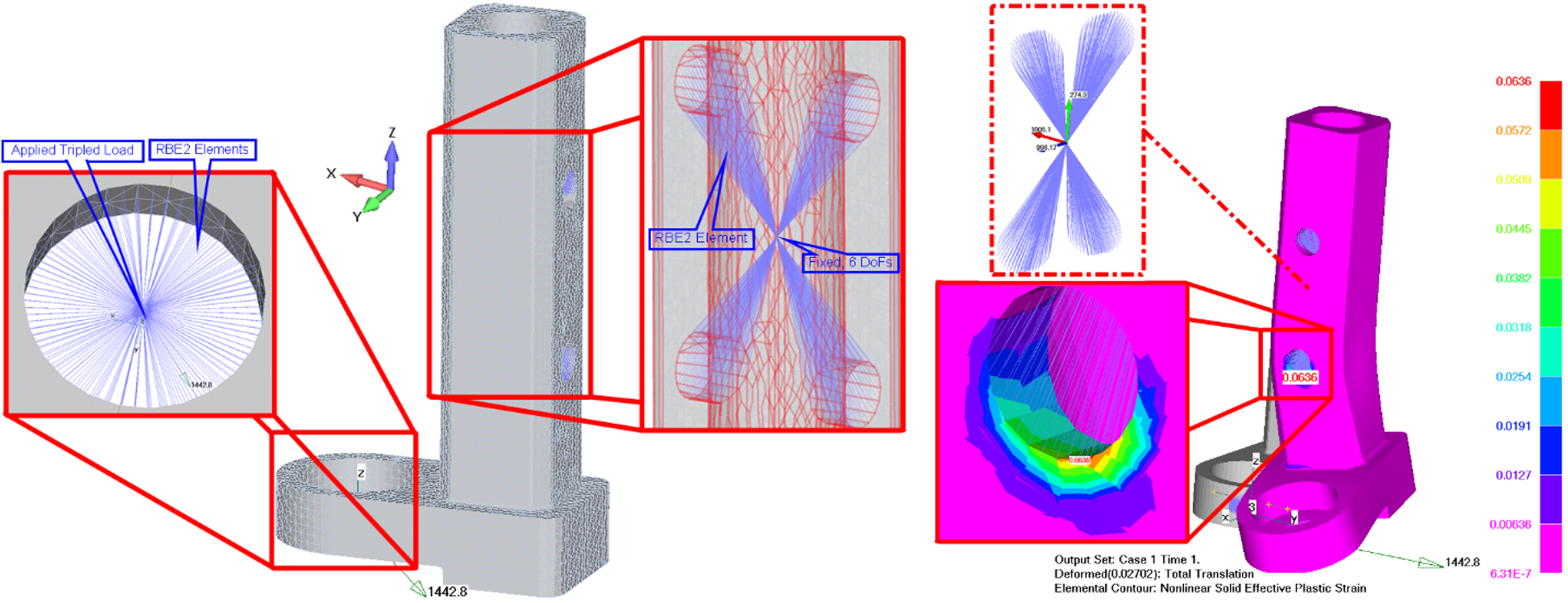
Tripled nonlinear-model loads
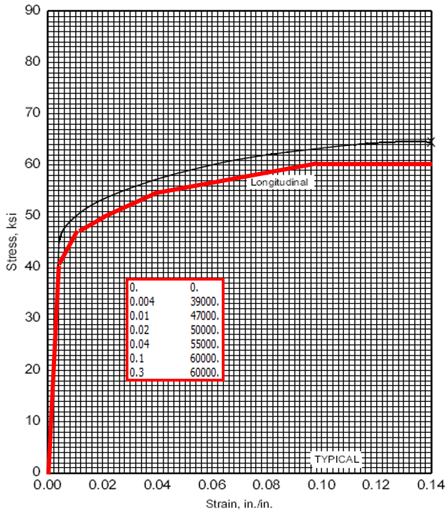
→ PASS
Equipment Support & Local Hand Calculations
The lowest rack bay carries the largest combined equipment mass (44.84 lbf after the source scaling assumptions), so it is selected for detailed equipment-support substantiation. This avoids repeating lower-demand installations while still demonstrating tray, beam, screw and rivet load paths.
HF Receiver / Exciter Group
The HF Receiver/Exciter, tray and mounting hardware are reduced to a 9.27 lbm support system with a 2.866 in CoG offset. The hand calculation treats the mounting tray as a simply supported beam and evaluates the five governing load directions. The 9 g forward inertial load is 83.43 lbf; maximum support reaction is 108.6 lbf. The governing XZ-plane bending moment is 239.11 in-lbf, giving 28.02 ksi bending stress in the 0.0625 in AL 2024-T3 CLAD mounting tray.
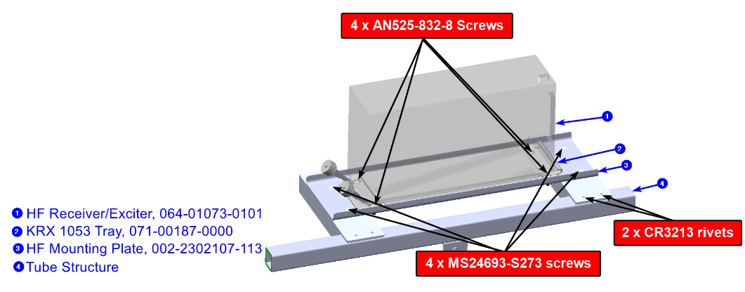
→ PASS
→ PASS
Artemis COMINT Group
A 3D rigid-body equilibrium model is used for the Artemis COMINT installation because the equipment/tray load is distributed through four mounting screws. The source reaction solution gives maximum screw shear of 24.9 lbf and maximum tension of 45.9 lbf in the forward case, compared with 1,020 lbf shear and 1,200 lbf tension allowables for the MS24693-S273 screws.
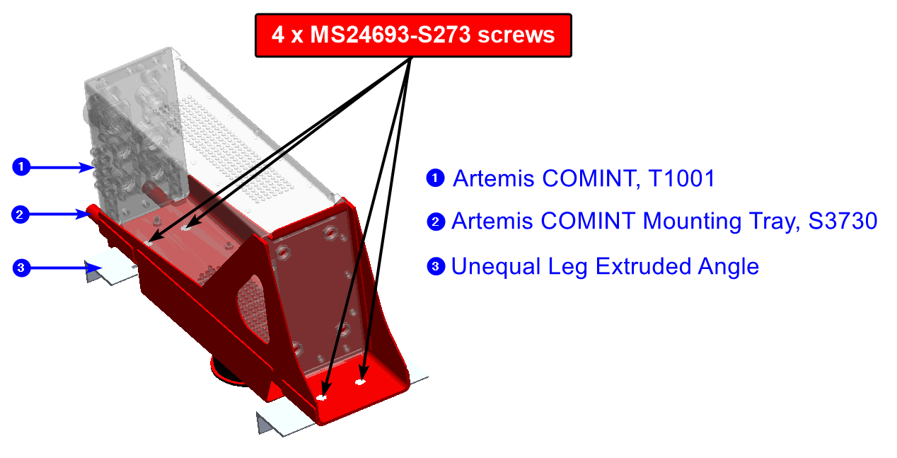
Rigid-body load distribution
The four-screw pattern is solved from force and moment equilibrium rather than assuming equal load sharing, preserving the effect of equipment CoG offset and fastener geometry.
SUBSTANTIATION OUTCOME
Heavier common configuration used to envelope the Power Rack.
Tube/weld strength, buckling and sheet-metal checks satisfy the source assessment.
Upper/lower studs, seat-track tooth and critical fasteners are substantiated by calculation or conservative comparison.
Critical lower-rack equipment groups are checked using reaction, beam and fastener substantiation.
Structural substantiation complete
The evaluated rack structure, attachment load paths and selected governing equipment installations satisfy the source report’s strength criteria for the assessed load cases.
REFERENCES
Structural Methods & Allowables
- MMPDS-15 - Metallic Materials Properties Development and Standardization
- Analysis & Design of Flight Vehicle Structures - E. F. Bruhn
- Aluminum Design Manual 2010
Regulatory & Aircraft Load Basis
- Federal Aviation Regulations - 14 CFR Part 25
- DHC-8-100 Load Cases and Applied Loads
Fasteners & Hardware Data
- NAS528 Fastener Codes
- CHERRYMAX Rivets technical data
- MS24693 technical data
- MS35206 technical data
- NAS1801 technical data
- NASM525 technical data
- NAS8602 technical data
- NASM3-20 technical data
Track & Stud Data
- FE200744 stud technical data
- ANCRA Clear Medium-Duty Aircraft Track - 40456-10-144 technical data
- ANCRA Threaded Stud - 40351 / 40352 technical data
- Installed-equipment manufacturer specification sheets cited in the source report