Each exhaust is treated as an external aerodynamic body with lift and drag resolved at its CoG.
INTRODUCTION
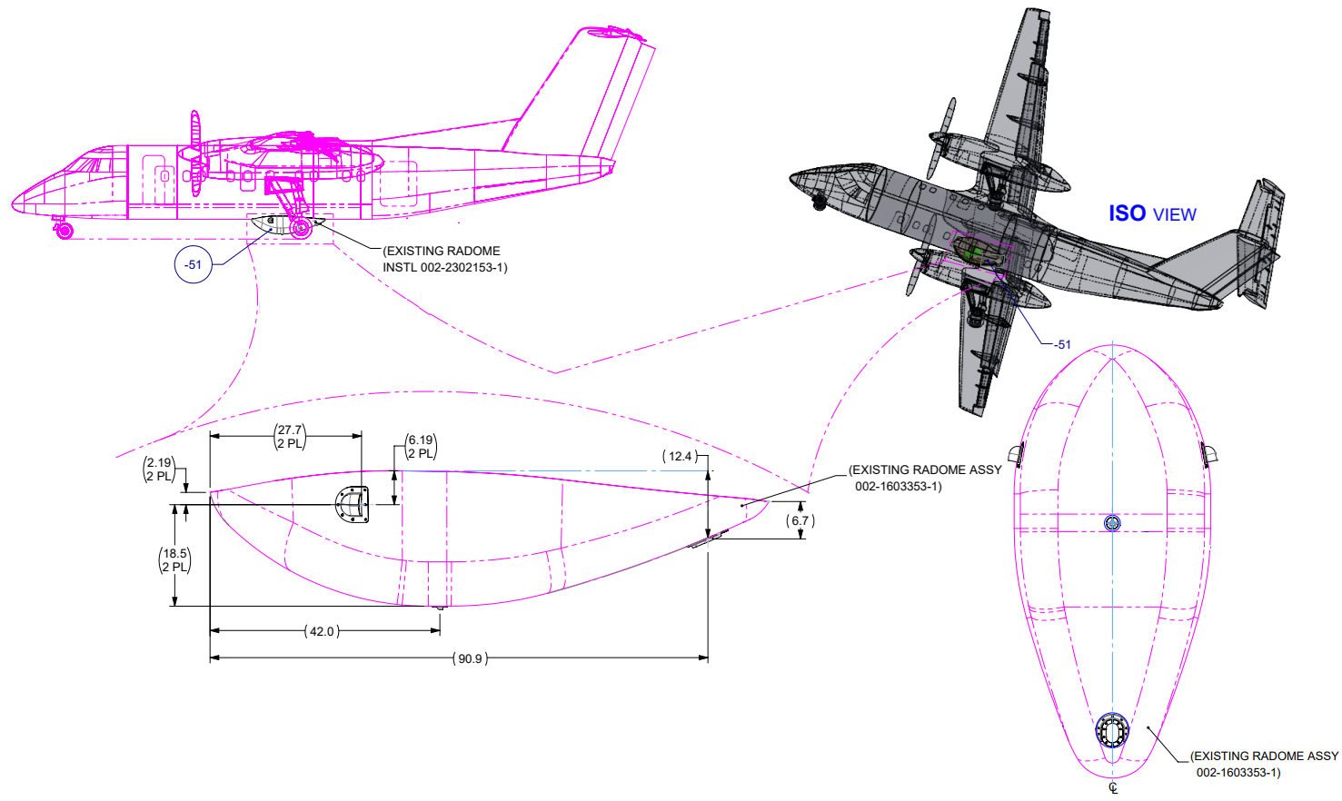
AIRCRAFTDHC-8-100Exterior radome modification
BOUNDING SPEED242 ktSea-level VMO,max = 408.45 ft/s
PRIMARY MATERIALSGlass/Epoxy + PTFEFiberglass Style 1581 / EPOCAST 50-1A; PTFE drain
SUBSTANTIATION ROUTEAero → Joints → LaminateRigid-body loads, CLPT, plate/shear and cut-out checks
Structural substantiation of the DHC-8-100 radome cooling-system installation. The assessment converts external aerodynamic demand into component attachment loads, develops conservative composite-joint allowables, and verifies the exhaust laminate, PTFE drain and radome cut-outs using 3D rigid-body equilibrium, CLPT, classical plate/shear methods and stress-concentration factors.
DESIGN ASSESSMENT
System Architecture & Load Path
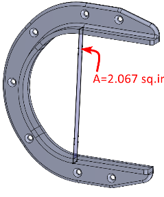
The exposed shield angle is assessed at the orientation that maximizes drag.
Aerodynamic load, fastener demand, annular-plate bending and outlet shear are checked separately.
Cut-out stress concentrations are assessed against the published radome laminate strengths.
I treated each cooling-system component as its own aerodynamic body because the exposed geometry and governing coefficient are different for the exhausts, aft-intake shield, and drain. Ultimate lift/drag is applied at each component CoG, the CoG offset is converted into attachment-plane moments, and the combined force/moment set is distributed to the fasteners with 3D rigid-body analysis. The joint check is then separated from the component-material check: the exhaust laminate is substantiated with CLPT, the PTFE drain with annular-plate bending and direct shear, and the radome interface with local cut-out stress-concentration factors. This preserves a traceable load path without forcing unlike failure mechanisms into one model.
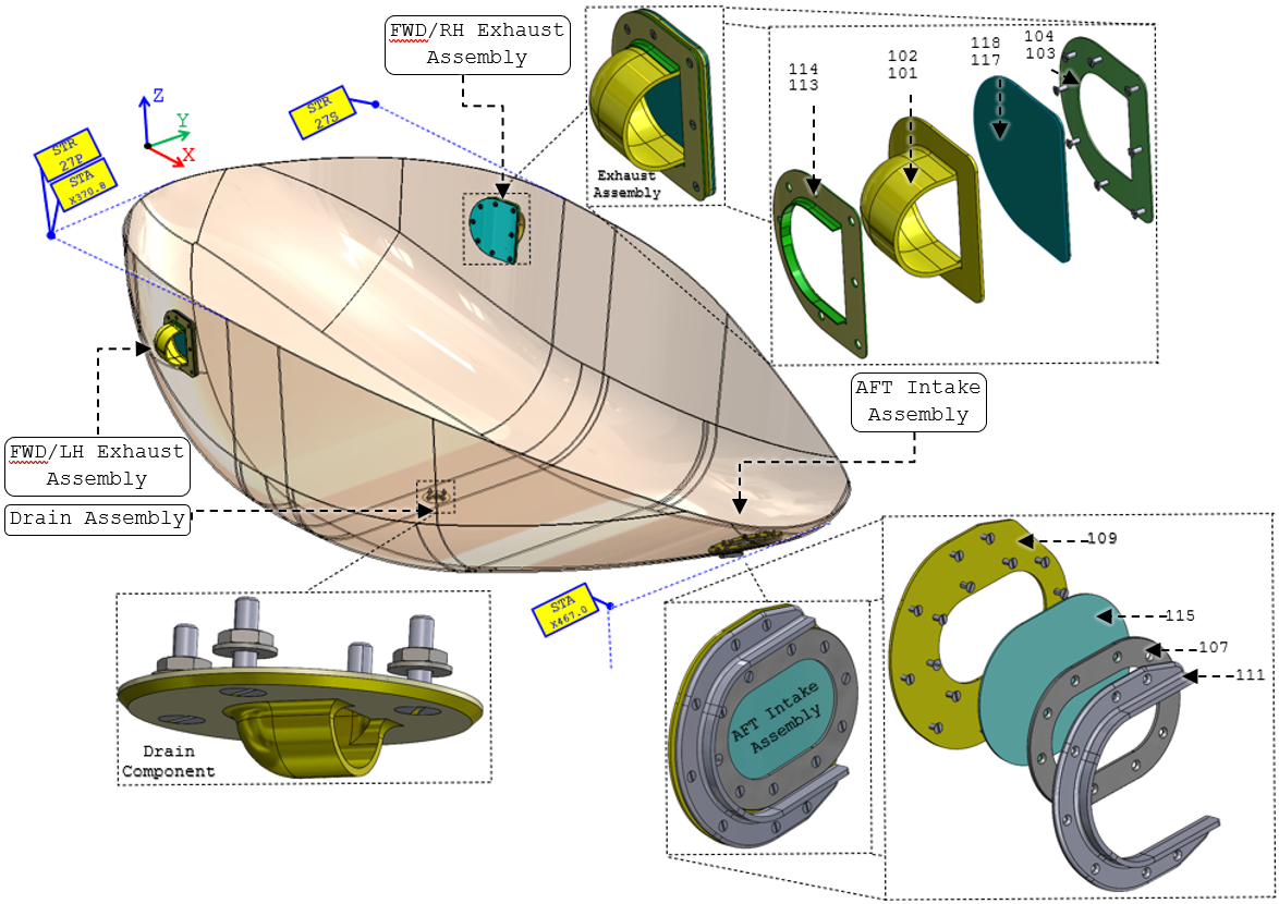
Structural components, material systems, thicknesses and laminate orientations.
| Component Name | Thickness [in] |
Material | No of Plies | Orientation |
|---|---|---|---|---|
| Meshes | 0.08 | Chemical-Resistant Polypropylene | - | - |
| Drain | 0.63 | PTFE | - | - |
| Flange Holders | 0.06 | Fiberglass Cloth - Style 1581 (MIL-C-9084) EPOCAST 50-1A Resin System and Hardener 9816 The Mixing Ratios, Application, and Curing Schedule are per the Manufacturer's Instructions. |
6 | 0°/45°/90°/0°/-45°/-90° |
| Flange Mesh Restrains | 0.125 | |||
| Intake Flange | 0.125 | 12 | 0°/45°/90°/0°/-45°/-90°/0°/45°/ 90°/0°/45°/90° | |
| LH & RH FWD Exhausts | 0.125 | |||
| Radome-Intake Flange | 0.125 | |||
| Shield Angle | 0.188 | 18 | 0°/45°/90°/0°/-45°/-90°/0°/45°/ 90°/ 0°/45°/90°/0°/ 45°/90°/0°/-45°/-90° |
Materials & Joint Allowable Basis
The installation combines a fiberglass/EPOCAST laminate with a PTFE drain and PTFE #10-32 attachment screws. Composite properties are treated as conservative hot-wet lower-bound values and reduced by an additional 25% for fabrication uncertainty before the laminate and joint checks.
Symmetric + balanced
Fiberglass Cloth Style 1581 is saturated with EPOCAST 50-1A / Hardener 9816. Wet layup is vacuum-assisted at approximately 20 inHg, cured overnight at room temperature and post-cured for 24 hours.
Hot-wet lower-bound philosophy
The source does not claim test-derived allowables for the as-built laminate. Instead, conservative hot-wet properties are selected and then reduced by an additional 25% to account for fabrication uncertainty.
Ftu1 = 32.11 ksi
Knocked-down laminate tensile strength in the material 1-direction.
Ftu2 = 25.75 ksi
Knocked-down tensile strength in the material 2-direction.
Fcu1 = Fcu2 = 36.14 ksi
Conservative compression strengths retained for the CLPT checks.
Fsu12 = 8.44 ksi
Knocked-down laminate shear strength used by the ply-level failure assessment.
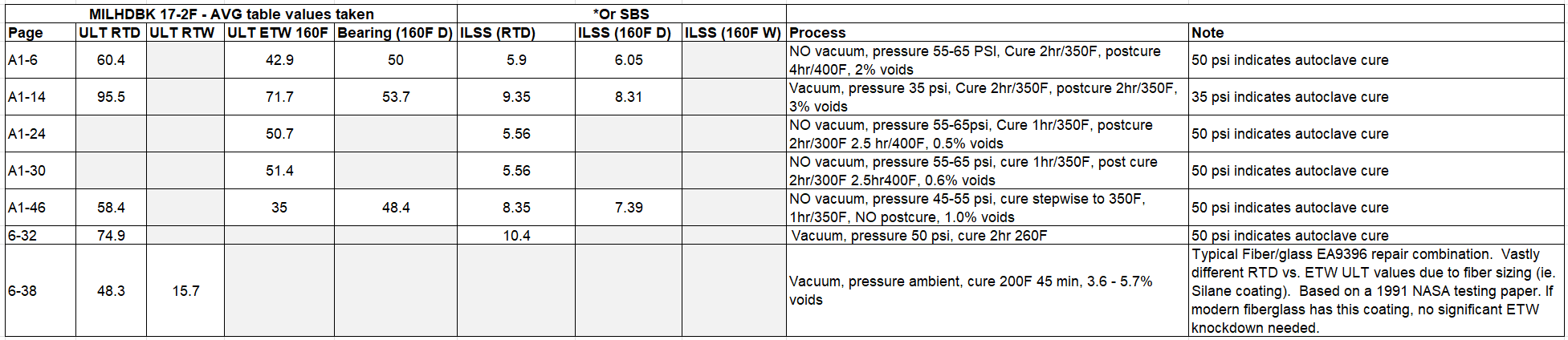
Interlaminar shear allowable: the cited fiberglass data span approximately 5.5–10.4 ksi. The analysis starts from the 6.5 ksi typical ILSS noted in the composite reference and applies the same 25% reduction, giving 4.875 ksi for the pull-through assessment.
Joint allowable philosophy
Evaluate the fastener and laminate/sheet as one load-transfer system. The usable joint allowable is the weakest physically applicable failure path.
Fastener shear alone does not define the joint.Composite bearing is corrected for geometry outside the test envelope.Pull-through is checked separately for out-of-plane demand.
Composite bearing treatment. A 40 ksi glass-laminate ultimate bearing basis is reduced when the installed joint falls outside the cited test envelope. The source applies edge-distance and small-diameter knockdowns, while no strength increase is credited for laminates thicker than the 0.118 in test baseline.
S17114 / 94701A833 · #10-32 PTFE countersunk screws
ThreadUNF-2A · ASME B18.6.3
Nominal shank0.19 in
Lengths1.0 in / 1.5 in
MaterialPTFE plastic
Conservative tensile basisFtu = Fty = 3.00 ksi
Shear strengthFsu = 0.725 ksi
For the installed PTFE screws, the shank/threads govern well before the surrounding composite bearing or pull-through limits. The source obtains the following isolated fastener capacities:
The composite pull-through check uses the Abbott semi-empirical relation with α = 0.75 for glass laminate and the knocked-down interlaminar shear value τmax = 4.875 ksi.
Composite-joint geometry used to determine bearing knockdown factors.
| Definition | Symbol | FWD/LH&RH Exhaust Assemblies | In the AFT Intake Assembly – Joint 1 | In the AFT Intake Assembly – Joint 2 |
|---|---|---|---|---|
| Accumulated thickness of all components | tjoint [in] | 0.06+0.125+0.125=0.31 | 0.125+0.125=0.25 | 0.125+0.188=0.313 |
| Shank diameter | Ds [in] | 0.19 | 0.19 | 0.19 |
| Thickness to diameter ratio | tjoint/Ds | 1.63 | 1.32 | 1.65 |
| Edge distance | e [in] | 0.5 | 0.5 | 0.44 |
| Edge distance to diameter ratio | e/Ds | 2.63 | 2.63 | 2.315 |
Knocked-down composite bearing capacity; pull-through = 2,400.56 lbf.
Knocked-down bearing capacity; pull-through = 1,469.41 lbf.
Knocked-down bearing capacity; pull-through = 2,467.3 lbf.
PTFE bearing capacity; still above the screw shear limit.
Ultimate in-plane and out-of-plane joint allowables used in the component checks.
| Assembly | In Plane Strength [lbf] |
Out of Plane Strength [lbf] |
|---|---|---|
| FWD/LH&RH Exhaust | 20.56 | 51.41 |
| AFT Intake – Joint 1 | 20.56 | 51.41 |
| AFT Intake – Joint 2 | 20.56 | 51.41 |
| Drain Component | 20.56 | 51.41 |
Source note: the original summary repeats “AFT Intake – Joint 1” for the third row; it is labeled “Joint 2” here to match the preceding joint definitions and calculations.
LOAD CASES FORMULATION
REGULATORY SOURCE BASISFAR Part 25 criteria used to formulate the structural load envelope
Flight-load framework
FAR 25.321 and 25.331–25.351
- General flight loads and symmetric maneuver response
- Flight maneuver envelope and design airspeeds
- Limit maneuver factors, gust and turbulence loads
- Fuel/oil, high-lift, rolling and yaw conditions
Emergency landing
FAR 25.561
- Forward: 9 g
- Downward: 6 g
- Upward: 3 g
- Sideward: 3 g airframe / 4 g seats & attachments
- Rearward: 1.5 g
This is an exterior modification, so the governing structural demand is established from flight aerodynamic loading rather than cabin emergency-landing inertia. I bounded the external shapes at sea-level maximum operating speed: the exhausts are treated as maximum-lift 2D external surfaces while retaining maximum drag, the aft-intake shield is aligned with the freestream to maximize drag, and the drain follows the same conservative lift/drag approach. The resulting aerodynamic forces are then multiplied by the source 1.5 ultimate factor before the attachment and material checks.
ρ = 0.00238 slug/ft³
Used to maximize dynamic pressure for the stated operating-speed assessment.
VMO,max = 242 kt
Equivalent to 408.45 ft/s. Each external shape is evaluated separately using the aerodynamic coefficient that best represents its geometry.
Bounding Aerodynamic Loads
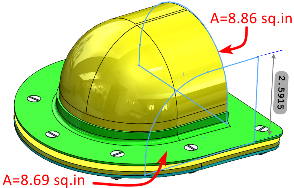
Each exposed component is idealized separately at the source sea-level maximum operating condition. Hoerner lift/drag data are used to define the governing coefficient for each geometry, and the resulting force is multiplied by the source 1.5 ultimate factor before structural assessment.
Bounding external aerodynamic loads retained for structural substantiation.
| Component | Idealization / coefficient | Ultimate lift [lbf] | Ultimate drag [lbf] |
|---|---|---|---|
| LH/RH FWD Exhaust | 2D lifting surface; CL=1.5, CD=0.1 | 26.96 | 1.83 |
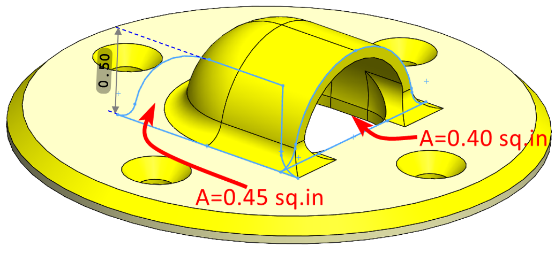
| AFT Intake Shield | Rear-open semicircular body; CD=1.20 | 0 | 5.13 |
| Drain | Small lifting/drag body; AR=0.556, CL,max=1.078, CD=0.1 | 1.003 | 0.083 |
CLASSICAL ANALYSIS
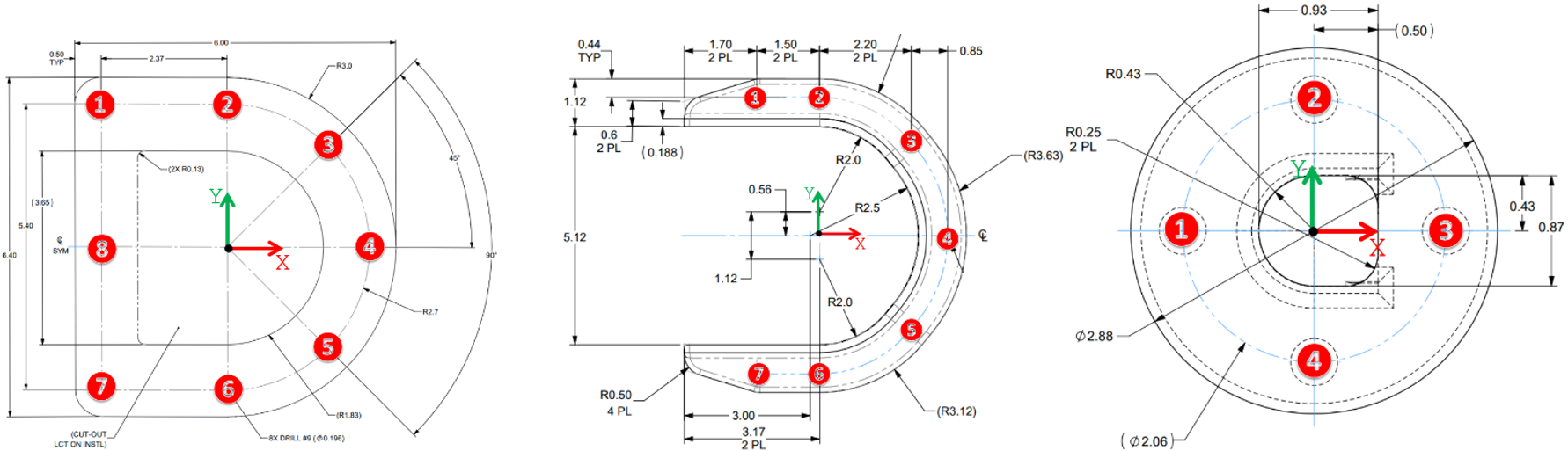
Ultimate aerodynamic loads are applied at each component CoG and transferred to the local fastener pattern. The offset between the force line of action and attachment plane generates the moments used in the component and laminate checks below.
Resolve lift/drag at the component CoG.
Apply CoG offsets to obtain Mx, My and Mz.
Distribute force and moment with 3D rigid-body analysis.
Compare joints, laminate/plate stresses and radome cut-out demand to allowables.
Load Transfer & Fastener Reactions
Ultimate forces are applied at each component CoG. The CoG offset generates attachment-plane moments, and the complete force/moment set is distributed to the local fastener group using 3D rigid-body equilibrium. The exhaust provides the largest attachment demand.
REPRESENTATIVE EXHAUST LOAD TRANSFERCoG (0.086, 0.001, 0.981) inL = 26.96 lbf · D = 1.83 lbf · Hmax = 2.965 in
Fastener Reaction Forces
Maximum 3D rigid-body fastener reactions from the source solutions.
| Assembly | Max shear [lbf] | Max tension [lbf] | Max compression [lbf] |
|---|---|---|---|
| Exhaust | 3.55 | 2.09 | 1.96 |
| AFT Intake | 0.73 | 0.10 | 0.11 |
| Drain | 0.25 | 0.01 | 0.01 |
GOVERNING FASTENER DEMANDExhaust attachment
Tension 2.09 lbf
Compression 1.96 lbf
Shear 3.55 lbf
PASS
Minimum joint capacities are 20.56 lbf in-plane and 51.41 lbf out-of-plane. Compressive reaction is distributed through the attachment surface.
Component Strength Assessment
Classical Laminate Plate Theory
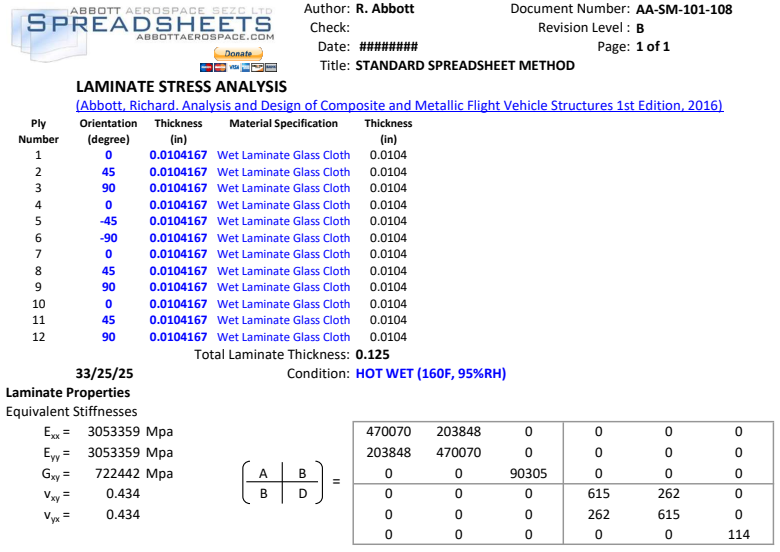
The laminate is characterized by its ABD stiffness matrix, then ply direct, bending and total stresses are recovered through the thickness.
Tsai-Wu · Hill · Hoffman
The source spreadsheet evaluates ply-level margins using multiple composite failure criteria rather than relying on a single scalar stress allowable.
Exhaust Component
LAMINATE0.125 in · 12 plies
STACK0/45/90/0/−45/−90/0/45/90/0/45/90°
LOAD INPUTAerodynamic forces + CoG moments
Non-flanged plate only
Only the 4.01 × 3.69 in non-flanged region is credited with carrying the aerodynamic load, increasing the running loads relative to using the full component area.
10× ultimate load/moment
The already-ultimate aerodynamic force and derived moments are increased tenfold to cover interference, rough-surface effects and additional drag forms.
Reacted at the exhaust base
The source excludes Mz from the plate CLPT input and assumes it is carried by the exhaust base interface.
25% laminate knockdown retained
Ply allowables already include the separate material knockdown established above.
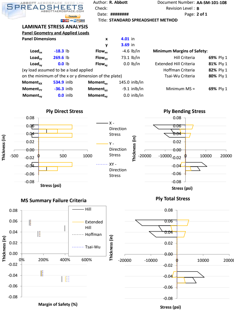
CLPT GOVERNING RESULTHill criterion
Minimum margin 69%
Laminate knockdown 25%
Applied load amplification 10×
PASS
The exhaust remains positive-margin after both the material-property knockdown and the separate tenfold amplification of ultimate aerodynamic forces and moments.
Drain Component
The PTFE drain is split into two mechanics problems: annular-plate bending at the base and direct shear through the outlet. This keeps the hand calculation aligned with the actual load path instead of forcing the full geometry into one idealization.
BASE IDEALIZATION
Annular plate · outer edge simply supported · inner edge free
A uniform line moment is applied at the inner radius. The Roark annular-plate coefficient is used at the inner edge where the tangential unit moment governs [Roark’s Formulas for Stress and Strain, 9th Ed., annular-plate case].
The source uses the more conservative coefficient for b/a = 0.3 and ν = 0.3 even though the PTFE Poisson ratio is 0.46.
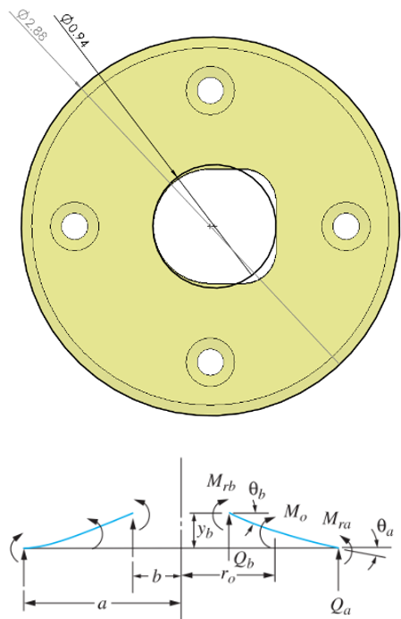
Drain base - PASSCalculated bending stress is 0.1033 ksi versus PTFE Fcy = 1.45 ksi; the source therefore reports a high positive margin.
The outlet portion of the drain component will be checked against shear loads. The load along the x- and y-axes equal 0.1003 lbf and 0.083 lbf, respectively. Hence, the shear stress at the XY surface is:
The ultimate shear strength for the PTFE Plastic is 725 psi. Therefore, it passes by observation.
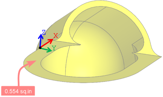
Radome’s Cut-Outs
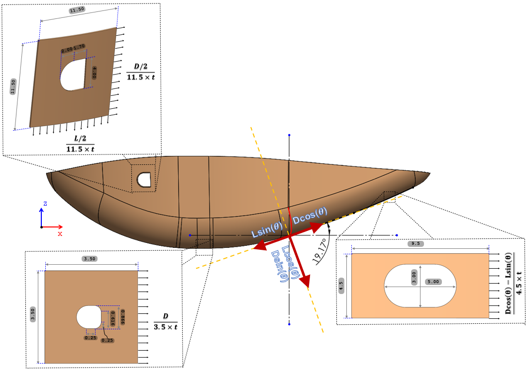
Four local openings are assessed as geometric stress raisers in the 0.1875 in radome laminate. Gross- or net-section stress-concentration factors are selected to match the cut-out geometry, then applied to the source far-field stresses.
Ktg
Peak edge stress referenced to gross far-field stress.
Ktn
Peak edge stress referenced to net-section far-field stress after the opening is removed.
The Exhaust Hole
Due to the sharp corner of the exhaust’s hole, it will be approximated as a 3.7”x4.0” rectangular hole with 0.125” corners. Considering a/b value of 0.925 and the minimum r/2b value of 0.05, the resulted Kt value is 4.62 [Peterson’s Stress Concentration Factors-3rd edition by Pilkey- Chart 4.62a]. The utilized r/2b is 0.033. Hence, the Kt value is scaled up by 25%. Therefore, Kt=4.62x1.25=5.78
The Drain Hole
The drain’s hole will be approximated as a 0.866” diameter circular hole due to its rounded corners. The resulted Ktg and Ktn values are 3.23 and 2.45, respectively [Peterson’s Stress Concentration Factors-3rd edition by Pilkey- Chart 4.1].
Aft Intake Hole
The aft intake hole has a slot-like shape. Considering a=1.5 and H=4.5, the resulted a/H value is 0.333. For conservatism, a/H value of 0.3 was used. The resulted Ktn value is 2.8 [Peterson’s Stress Concentration Factors-3rd edition by Pilkey- Chart 4.59].
Gross/net stress-concentration factors selected for the three cut-out geometries.
| Reference | ||||
|---|---|---|---|---|
| Exhaust’s hole | - | - | 5.78 | [Peterson’s Stress Concentration Factors-3rd edition by Pilkey- Chart 4.62a] |
| Drain’s hole | 3.23 | 2.45 | - | [Peterson’s Stress Concentration Factors-3rd edition by Pilkey- Chart 4.1] |
| Aft intake’ hole | - | 2.8 | - | [Peterson’s Stress Concentration Factors-3rd edition by Pilkey- Chart 4.59] |
RADOME CUT-OUT ASSESSMENTLocal stress-concentration check
Highest tabulated stress 9.54 ksi
Minimum tensile strength 22 ksi
Minimum compressive strength 25 ksi
PASS
The accompanying stress table lists the AFT intake cut-out at 9.5368 ksi, while the source narrative identifies 5.77 ksi at the exhaust cut-out. Both values remain below the published radome laminate strength basis used by the source assessment.
Calculated concentrated stresses at the radome cut-out edges.
| Considering | |||
|---|---|---|---|
| Exhaust’s hole | 5768.44 | ||
| Drain’s hole | 637 | 642 | |
| Aft intake’ hole | 9536.8 | ||
SUBSTANTIATION OUTCOME
Governing 3.55 lbf shear / 2.09 lbf tension is below the 20.56 / 51.41 lbf source joint allowables.
Minimum source CLPT margin by Hill criterion after 25% material knockdown and 10× aerodynamic amplification.
Base bending stress = 0.1033 ksi versus Fcy=1.45 ksi; outlet shear = 1.82 psi versus 725 psi.
Highest tabulated concentrated stress = 9.5368 ksi versus 22 ksi tensile / 25 ksi compressive strength basis.
Structural substantiation complete
The source assessment demonstrates positive reserve for the evaluated aerodynamic load path, fastener groups, composite exhaust laminate, PTFE drain and radome cut-outs.
REFERENCES
Composite Materials & Analysis Methods
- Composite Materials Handbook - MIL-HDBK-17 / CMH-17
- Analysis & Design of Composite & Metallic Flight Vehicle Structures - Richard Abbott
- Lamina Stress Analysis - Document AA-SM-101-108
- The Strength of Bolted Joints in Multidirectional CFRP Laminates
- Roark’s Formulas for Stress and Strain - 9th Edition
- Peterson’s Stress Concentration Factors - 3rd Edition
Regulatory & Aerodynamic Load Basis
- Federal Aviation Regulations - 14 CFR Part 25
- Fluid-Dynamic Lift - S. F. Hoerner
- Fluid-Dynamic Drag - S. F. Hoerner
Composite Fabrication & Material Data
- MIL-C-9084 - Fiberglass Cloth specification
- MIL-P-22241B - Polytetrafluoroethylene plastic sheet and film
- EPOCAST 50-1A Resin System / Hardener 9816 manufacturer instructions
- PTFE material and sheet technical data cited in the source report
Fastener, Washer & Aircraft Structure Data
- ASME B18.6.3 - Machine screw dimensional standard
- S17114 / 94701A833 screw technical data
- 93785A500 washer technical data
- SRM-100 - General X-Band Nose Radome Repair Procedures