DHC-8-315Static StressAerodynamic LoadsCabin PressurizationDoubler ReinforcementSwift Load DistributionFastener AllowablesMargins of Safety
Introduction
Description of the Modification
AircraftDHC-8-315Ventral fuselage installation
ModificationTwo AV-265 antennasForward and aft structural provisions
Primary reinforcement2024-T3 external doublers0.8 in feed-through cutouts
AssessmentAerodynamic + pressure + joint loadsHand substantiation and Swift load distribution
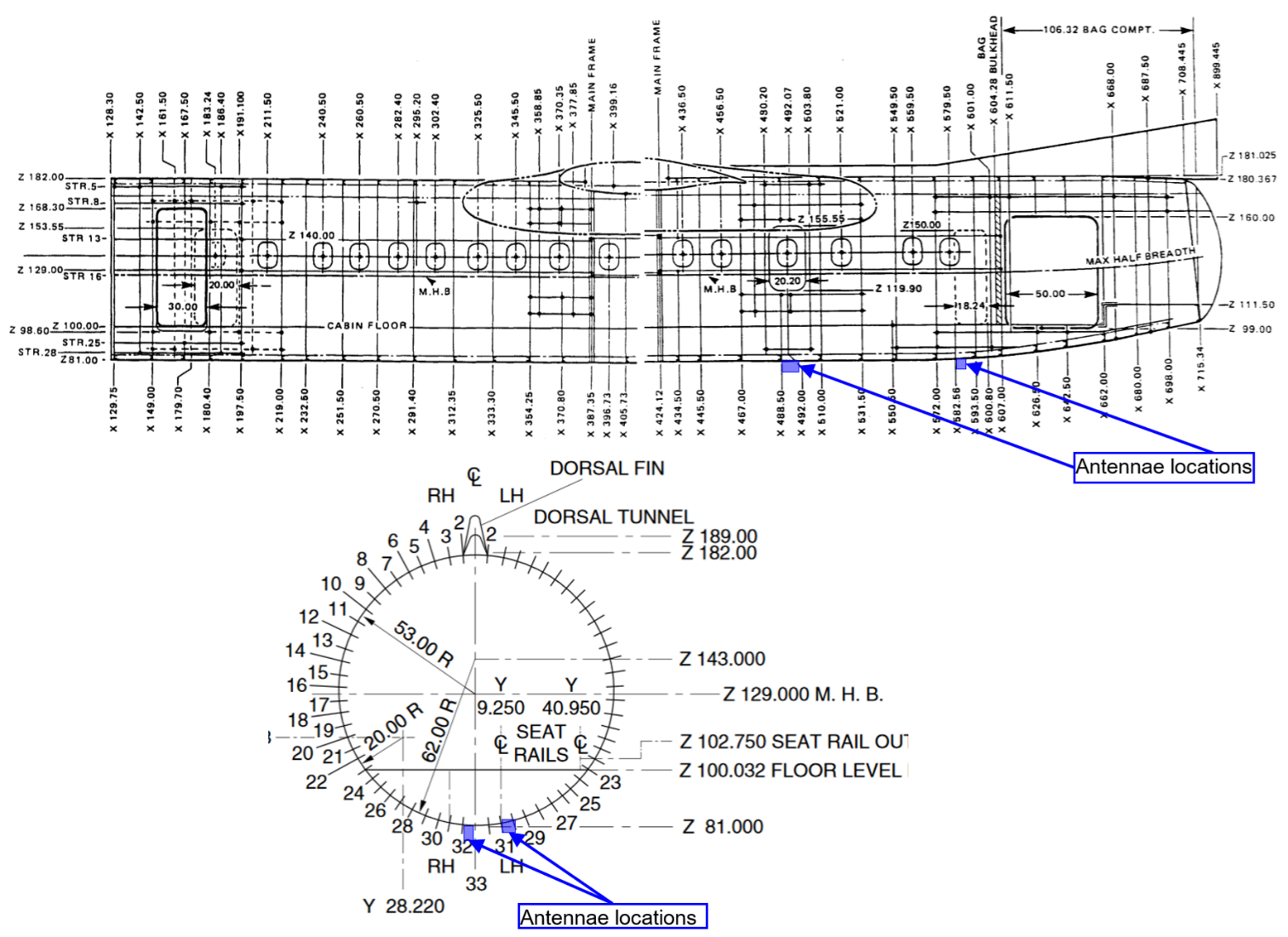
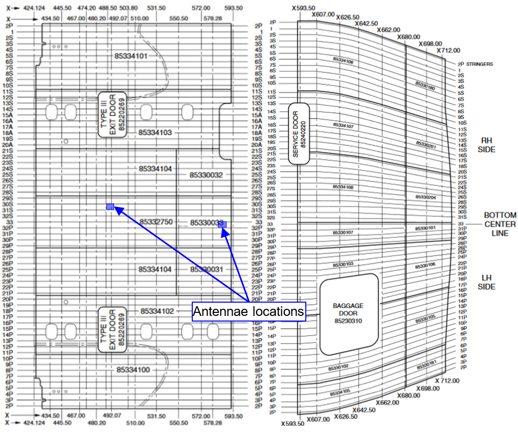
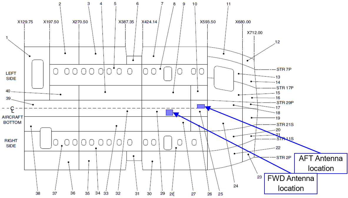
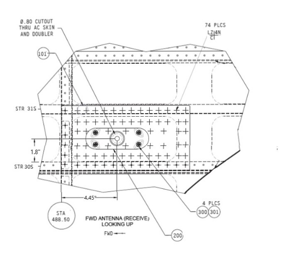
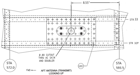
Two AV-265 antennas are installed on the lower fuselage: the forward antenna is aft of X488.5 between STR 30S and STR 31S, while the aft antenna is forward of X589.00 between STR 32P and STR 33.
FEED-THROUGHØ 0.8 in fuselage cutout
Each antenna requires a local cable penetration through the fuselage skin.
REINFORCEMENTExternal aluminum doubler
The doubler restores local load-carrying capability around the cutout and distributes skin loads into the surrounding rivet pattern.
DOUBLER ATTACHMENTNAS1097AD flush rivets
The forward pattern uses 74 rivets and the aft pattern uses 58, reflecting the local geometry and required load-transfer path.
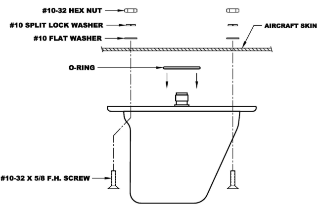
ANTENNA ATTACHMENT4 × NAS8604-6 screws
Each antenna is mounted with 100° countersunk alloy-steel screws to retain the external aerodynamic profile.
Load-Path Rationale
I separated the direct antenna-attachment path from the fuselage pressure-load redistribution path because they answer different structural questions. Inertial and aerodynamic blade loads enter through the four NAS8604-6 mounting screws and are checked directly against the attachment hardware and local substrate capacity. Cabin pressure acts as far-field hoop and longitudinal membrane loading in the skin; the external doubler then restores load-carrying capability around the feed-through, and the NAS1097AD rivet rows transfer part of that load into the doubler. Swift strain-compatibility DCLR/LDF calculations are used to quantify how much load reaches the doubler center and how much enters through the first rivet row before skin, doubler, rivet, and corner-bearing margins are checked separately. This keeps the load path explicit and avoids mixing direct antenna loads with pressure-driven skin redistribution.
Installation location and fuselage context
Fuselage stations diagram for DHC-8-315 aircraft showing the FWD and AFT antennae installation locations
Fuselage stations diagram for DHC-8-315 aircraft showing the FWD and AFT antennae installation locations
Center Fuselage Skin Identification from X 129.75 to X 712.00.
Local installation geometry and hardware
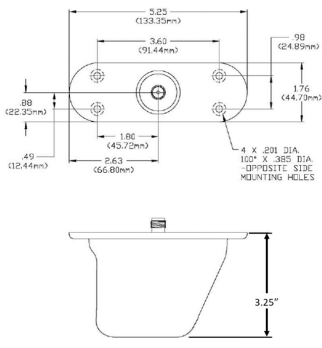
AV-265 Antenna Installation details
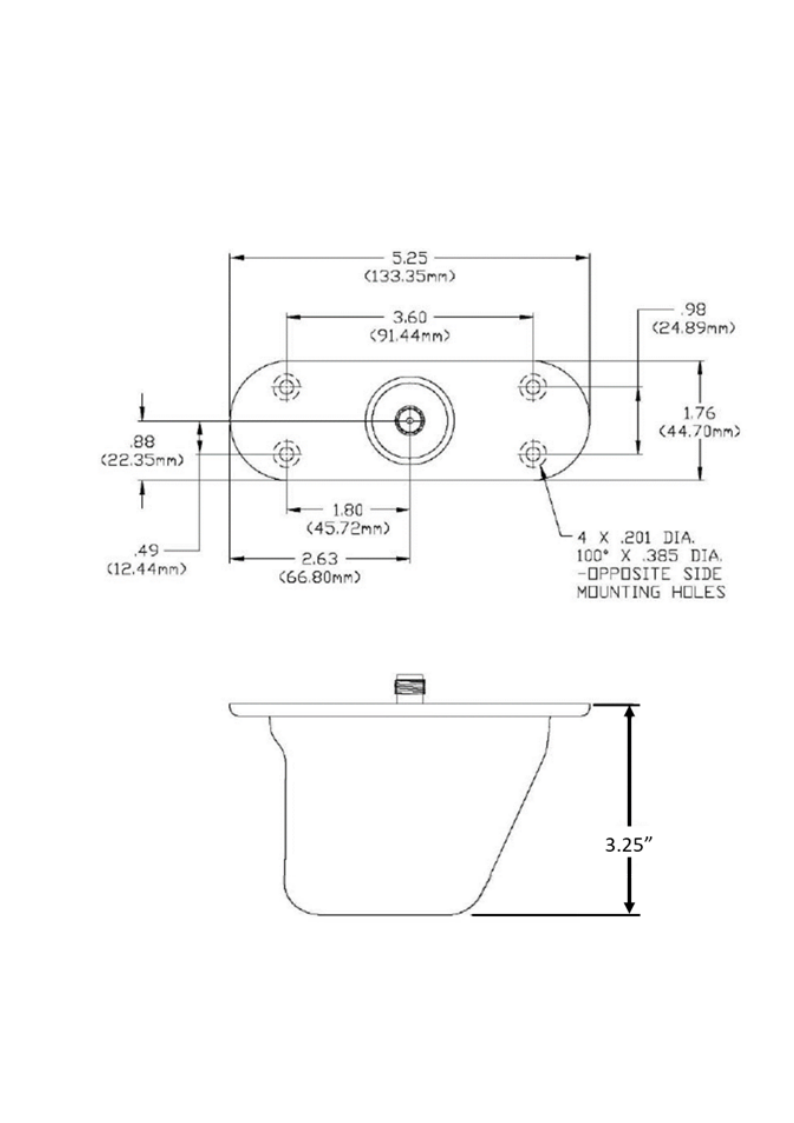
AV-265 Antenna dimensions and Installation Layout
Mechanical Properties and Material Specifications for
Aircraft Antenna Installation Components.
Description
Location
Size
Material
Stu
Ssu
Sbru
E
µ
ksi
-
Fuselage Skin
AFT
0.032
Alclad 2024−T3/T42
60
37
121
10.5 x10³
0.33
Fuselage Waffle
0.028
Doubler
0.071
Alclad 2024−T3
62
38
125
Fuselage Skin
FWD
0.032
60
37
121
Fuselage Waffle
0.028
Doubler
0.05
Blanking plate
-
0.09
62
38
125
-
-
Where:
Stu : Ultimate tension strength.
Ssu : Ultimate shear strength.
Sbru : Ultimate bearing strength.
E : Young modulus of elasticity.
µ : Poisson’s ratio.
Dimensions and Parameter Specifications for Forward and Aft
Antenna Installations on Aircraft.
Unit
FWD Antenna
AFT Antenna
Fuselage
Thickness
in
0.06*
0.06*
Cutout area
in2
0.5027
0.5027
Cutout Diameter
in
0.8
0.8
Fuselage maximum radius (R)
in
62
62
Doubler
Thickness
in
0.05
0.071
Dim, hoop direction (W)
in
5.4
5
Dim, longitudinal direction (L)
in
10.7
8.8
AV-265
Weight
lbf
0.4
0.4
Dim, longitudinal direction (L)
in
5.25
5.25
Dim, hoop direction (W)
in
1.8
1.8
Height
in
3.25
3.25
Cabin
Maximum pressure differential (∆P)
psi
5.95
teff
Effective fuselage thickness = 0.060 in
The bonded 0.032 in skin and 0.028 in waffle are treated as one load-carrying section. The combined thickness is used for pressure stress and local load-transfer calculations at both antenna provisions.
Design Assessment
Critical Loading Condition
REGULATORY SOURCE BASISEmergency and maneuver load criteria used for the installation
FAR 23.561 · Emergency landing
Upward: 3.0 g
Forward: 9.0 g
Sideward: 1.5 g
Downward: 3.0 g
Governing downward case
FAR 23.337(a)(1) maneuvering factor:
Because 5.7 g exceeds the 3.0 g emergency downward value, 5.7 g governs downward.
Load-Case Selection Rationale
I treated the installation with three bounding load families because each acts through a different mechanism. For direct antenna inertia, the FAR 23.561 emergency conditions are retained, except the downward direction where the 3.8 g positive maneuver factor multiplied by 1.5 gives 5.7 g ultimate and therefore exceeds the 3.0 g emergency value. For the exposed antenna blade, the aerodynamic check is bounded at dive speed, VD = 1.25 VMO = 303.75 kn, rather than normal operating speed. For the fuselage reinforcement, cabin pressure is treated separately with the source ultimate pressure differential of 11.87 psi. This prevents unrelated load paths from being combined while retaining the governing demand for each failure mode.
Selected governing load conditions used in the structural assessment.
Case
Condition
Source / candidate value
Selected design value
Governing basis
1
Upward inertia
3.0 g
3.0 g
Emergency landing
2
Forward inertia
9.0 g
9.0 g
Emergency landing
3
Sideward inertia
1.5 g
1.5 g
Emergency landing
4
Downward inertia
3.0 g emergency / 5.7 g maneuver
5.7 g
Maneuver load governs
5
Aerodynamic envelope
VMO = 243 kn
VD = 303.75 kn
Dive-speed aerodynamic bound
6
Cabin pressure
ΔP = 5.95 psi
Pult = 11.87 psi
Ultimate pressurization
Antenna Blanking Plate Installations
✓
Blanking plates - passed by inspection
Each previously approved provision is closed with a 0.090 in AL 2024-T3 plate secured by four NAS8604-6 #10-32 screws. With negligible applied loading and an existing approved structural provision, no separate detailed strength calculation is required by the source assessment.
Inertial Loading Considerations
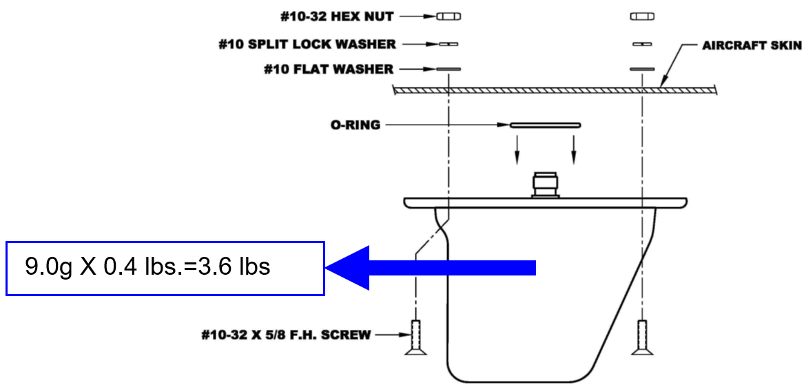
Antenna weight0.4 lbf
9 g forward inertia3.6 lbf
NAS8604-6 shear allowable720 lbf
NAS8604-6 tensile allowable1,200 lbf
Substrate bearing strength121–125 ksi
Why inertia is non-governing. The 3.6 lbf emergency forward load is orders of magnitude below the screw shear/tension capacities, and the supporting aluminum layers have high bearing allowables. The source therefore passes the direct antenna inertia path by inspection.
AV-265 Antenna Critical Emergency Landing Load
Aerodynamic Loading Considerations
Lift Force
LOAD ORIENTATION
Side load normal to the flight path
The aerodynamic side force is treated perpendicular to the antenna’s forward trajectory to capture a conservative cross-flow condition.
AIRFOIL IDEALIZATION
Symmetric section
The blade is idealized as a symmetric airfoil so established lift/drag relations can be used with the scaled antenna geometry.
DESIGN SPEED
Dive speed, not VMO
The analysis uses VD = 1.25 VMO per the cited FAR criterion, increasing dynamic pressure relative to normal operating speed.
CONSERVATIVE PROFILE
NACA 0012 envelopes the scaled section
The scaled thickness ratio is about 8.63%, closer to a thinner NACA 0004-type profile; NACA 0012 is selected because its higher lift coefficient produces a conservative aerodynamic load.
The dive speed used for the aerodynamic assessment is:
Conservative design speed
[FAR 23.335(b)(1)]
Scaled antenna geometry gives the following mean section properties:
Mean antenna geometry
NACA
NACA 0012 selected as the conservative aerodynamic surrogate
The measured mean thickness ratio is 8.63%. Using the thicker symmetric NACA 0012 profile intentionally biases the lift estimate upward relative to the thinner profile suggested by the scaled geometry.
Reynolds number is based on dive speed, mean chord and conservative sea-level kinematic viscosity:
Reynolds number
ν = 1.46×10⁻⁵ m²/s is the source’s conservative sea-level air value.
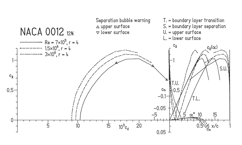
NACA 0012 source data
cl,max 1.1744cd,max 0.017821αstall 12.18°
The slope of the
curve can be calculated as below.
Characteristic data for NACA 0012 airfoil [Airfoil Design and Data by Richard Eppler]
The antenna’s span equals: .
Considering the antenna as a trapezoid, the antenna’s surface area
equals,
The aspect ratio of the antenna can be calculated as below
[Fundamentals of Aerodynamics 3rd Edition by John D Anderson]:
Assuming that the antenna has an elliptical lift distribution, the
slope of the
curve of the 3D antenna ()
can be approximated as below [Fundamentals of Aerodynamics 3rd Edition by John D Anderson-Page 380]:
The slope ()
can also be expressed as below.
Hence, the maximum lift coefficient, ,
of the antenna can be calculated as below:
The ultimate aerodynamic side force acting on the anntenna equals the
lift force generated on it, namelly;
Moreover, each of the four NAS8604-6 screws securing each antenna
will have a shear load of:
Which is very low compared with the allowable ultimate shear load of
the NAS8604-6 screw. It’s obvious that the resultant margin of safety
will be very high, and all antenna attachment hardware and supporting
structures are passed by inspection for aerodynamic ultimate lift
loading.
Drag Force
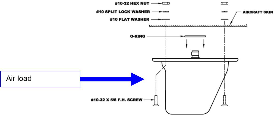
The drag load is resisted through the same four-screw antenna interface and transferred into the reinforced fuselage provision shown below.
Air (Drag) load acting on AV-265 Antenna
Assuming that the antenna has an elliptical lift distribution, the
maximum drag coefficient of the 3D antenna ()
can be approximated as below [Fundamentals of Aerodynamics 3rd Edition by John D Anderson]:
Where
is the maximum drag coefficient of the antenna’s airfoil,
is the maximum induced drag coefficient (drag due to lift) of the
antenna, which can be calculated as below:
Hence, the maximum drag coefficient of the 3D antenna ()
is:
The ultimate aerodynamic drag force acting on the anntenna
equals;
Moreover, each of the four NAS8604-6 screws securing each antenna
will have a shear load of:
Which is very low compared with the allowable ultimate shear load of
the NAS8604-6 screw. It’s obvious that the resultant margin of safety
will be very high, and all antenna attachment hardware and supporting
structures are passed by inspection for aerodynamic ultimate drag
loading.
The source applies FAR 25.303 and 25.365(d), including the 1.5 strength factor and 1.33 pressure multiplier, to obtain the ultimate pressure differential used below.
Conservative load combination. At the ventral fuselage, flight bending places the skin in compression and therefore relieves pressure-induced tensile stress. The bending contribution is omitted so the pressure-only tensile state remains conservative for this local check.
Total Far-Field Hoop and Longitudinal Stresses in the Skin
Using the bottom-fuselage radius = 62 in and the effective 0.060 in skin-plus-waffle thickness, the pressure-induced far-field stresses are:
Total Far-Field Hoop and Longitudinal Loads Across the Doubler
The total far field hoop and longitudinal loads
across the doubler’s hoop and longitudinal directions can be expressed
as:
FWD antenna location:
AFT antenna location:
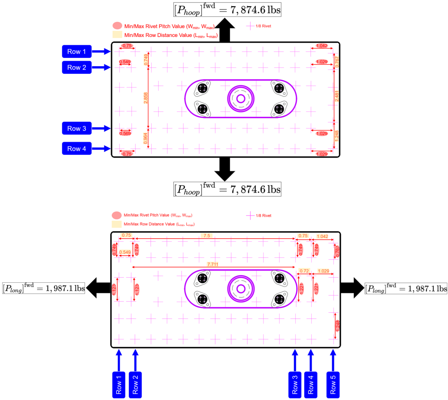
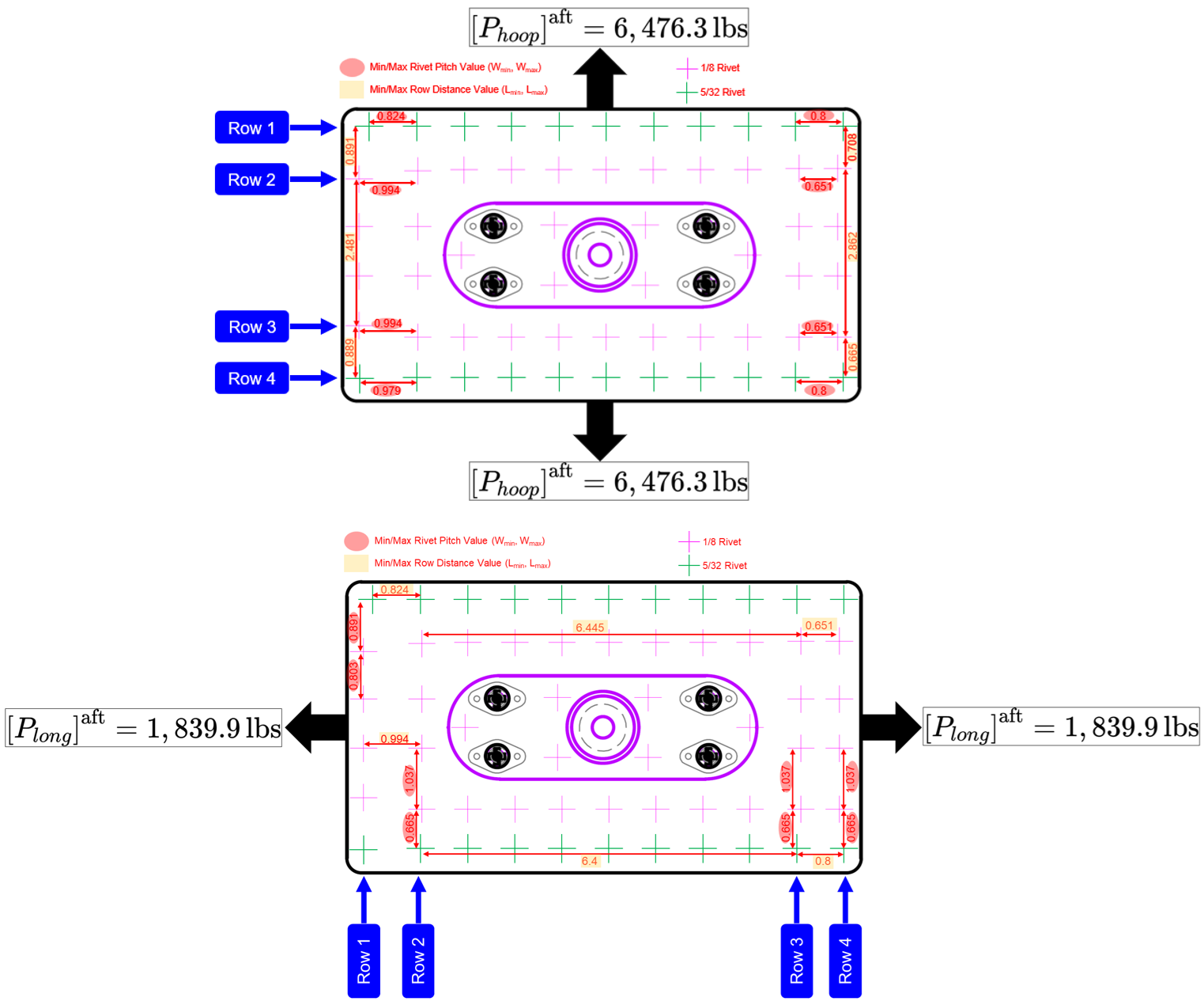
Doubler Central Load Ratio (DCLR) and First-Row Load Distribution Factors (LDF)
DCLR
Load reaching the doubler center
The Doubler Central Load Ratio represents the fraction of the far-field hoop or longitudinal load accumulated at the doubler center after progressive transfer through the rivet rows.
1st-row LDF
Critical first-row fastener demand
The first-row Load Distribution Factor represents the fraction of the applied directional load entering the doubler through the first rivet row-the row used to establish the critical individual fastener load.
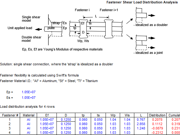
Swift
Swift strain-compatibility method
The source uses the Fastener Shear Load Distribution Analysis tool based on Swift’s strain-compatibility formulation to capture progressive shear transfer through the joint rather than assuming uniform load per rivet. [Damage Tolerance Assessment Handbook-Volume II: Airframe Damage Tolerance Evaluation]
Ep, Es, EfPlate, doubler and fastener elastic moduli
D / materialRivet diameter and material
tp, tsSkin and doubler thicknesses
Wp, WsFastener pitch across the evaluated row
LDistance between adjacent rivet rows
Why multiple cases are required. Rivet pitch and row spacing vary around the doubler, so both minimum and maximum geometric combinations are evaluated. The aft provision is also solved for both 1/8 in and 5/32 in rivets. This brackets the stiffness/load-transfer sensitivity instead of relying on one nominal joint geometry.
Calculating the Doubler Central Load Ratio (DCLR) and the 1 st row Load Distribution Factors (LDF)
Free Body Diagram (FBD) for the antenna installation in the FWD region for the hoop and longitudinal cases.
Free Body Diagram (FBD) for the antenna installation in the AFT region for the hoop and longitudinal cases.
Doubler Central Load Ratio (DCLR) and the 1st row
Load Distribution Factors (LDF) for various case-scenarios for both the
FWD and AFT antenna installation locations.
AFT antenna installation location
Load Direction
Hoop
Longitudinal
Hoop
Longitudinal
Rivet Size (in)
1/8
5/32
Parameter (%)
Wmax, Lmax
25.19
36.85
28.11
43.41
26.64
38.60
29.31
44.68
Wmin, Lmin
26.22
39.44
29.85
46.70
27.57
41.03
30.93
47.66
FWD antenna installation location
Wmax, Lmax
20.78
31.9
23.42
39.05
Wmin, Lmin
24.44
36.07
24.66
41.27
Hoop and Longitudinal Loads Transferred to the Doubler and Skin Center
Considering the case of 1/8” rivet size with maximum values of rivet’
pitch (Wmax) and rows distances (Lmax), we can
calculate the total hoop/longitudinal loads transferred to the
doubler’s center as follows:
Where
is the total far field hoop and longitudinal loads across the doubler’s
hoop and longitudinal directions.
FWD antenna location:
AFT antenna location:
Consequently, the total hoop/longitudinal loads transferred
to the skin center for the same case can be calculated
as:
FWD antenna location:
AFT antenna location:
The same load-transfer calculation is repeated for every evaluated geometry/rivet-size case; the resulting doubler-center and skin-center loads are summarized in the two tables below.
Total hoop/longitudinal loads (lbf) transferred to the doubler center, , for the evaluated FWD and AFT joint cases.
AFT antenna installation location
Rivet Size (in)
1/8
5/32
Load Direction
Hoop
Longitudinal
Hoop
Longitudinal
Wmax, Lmax
2,386.52
798.70
2,499.85
822.07
Wmin, Lmin
2,554.25
859.23
2,657.23
876.90
FWD antenna installation location
Wmax, Lmax
2,512.00
775.96
Wmin, Lmin
2,840.37
820.08
Total hoop/longitudinal loads (lbf) transferred to the skin center, , for the evaluated FWD and AFT joint cases.
AFT antenna installation location
Rivet Size (in)
1/8
5/32
Load Direction
Hoop
Longitudinal
Hoop
Longitudinal
Wmax, Lmax
4,089.78
1,041.20
3,976.45
1,017.83
Wmin, Lmin
3,922.05
980.67
3,819.07
963.00
FWD antenna installation location
Wmax, Lmax
5,362.60
1,211.14
Wmin, Lmin
5,034.23
1,167.02
Adjusted Hoop and Longitudinal Stresses at the Doubler and Skin Center
Net-section basis. The critical section passes through the feed-through and fastener holes, so the effective width and length are reduced for removed material before the center loads are converted into adjusted stresses. The AFT calculation conservatively uses the 5/32 in rivet diameter when defining the net section.
Where
is the maximum number of rivets along the direction of interest,
is the largest rivet’s diameter exist along the direction of interest,
is the cutout diameter. Conservatively, 5/32” rivet size was used in the
AFT antenna location.
FWD antenna location:
AFT antenna location:
Considering the case of 1/8” rivet size with maximum values of rivet’
pitch (Wmax) and rows distances (Lmax), we can
calculate the ADJUSTED far field hoop and longitudinal
stresses in the skin using:
and
FWD antenna location:
AFT antenna location:
Similarly, the ADJUSTED far field hoop and
longitudinal stresses in the doubler can be calculated
using:
and
FWD antenna location:
AFT antenna location:
The same net-section calculation is repeated for every evaluated case; the adjusted skin and doubler stresses are summarized in the two tables below.
Adjusted far-field hoop and longitudinal stresses (ksi) in the skin for the evaluated FWD and AFT joint cases.
AFT antenna installation location
Rivet Size (in)
1/8
5/32
Load Direction
Hoop
Longitudinal
Hoop
Longitudinal
MAX (W, L) values
10.8518
5.5866
10.5511
5.4612
MIN (W, L) values
10.4068
5.2618
10.1335
5.1670
FWD antenna installation location
MAX (W, L) values
10.9665
5.2430
MIN (W, L) values
10.2949
5.0520
Adjusted far-field hoop and longitudinal stresses (ksi) in the doubler for the evaluated FWD and AFT joint cases.
For both antenna locations, the critical skin stress occurs with maximum pitch/row spacing and the 1/8 in rivet case. The corresponding minimum margins are calculated below.
The doubler is governed by the minimum pitch/row-spacing case; the aft 5/32 in rivet case produces the highest local doubler hoop stress. The resulting margins are calculated below.
FWD antenna location:
AFT antenna location:
Individual Hoop and Longitudinal Load per Rivet
The individual hoop and longitudinal load per rivet carried by the
first row of fasteners can be expressed as:
Where
the number of rivets implicated in load redistribution.
FWD antenna location:
AFT antenna location:
The first-row fastener calculation is repeated for every evaluated case, with the directional load per rivet summarized below.
First-row hoop/longitudinal load per rivet (lbf), , for the evaluated FWD and AFT joint cases.
AFT antenna installation location
Rivet Size (in)
1/8
5/32
Load Direction
Hoop
Longitudinal
Hoop
Longitudinal
MAX (W, L) values
148.31
86.20
156.84
89.88
MIN (W, L) values
154.37
91.54
162.32
94.85
FWD antenna installation location
MAX (W, L) values
116.88
77.56
MIN (W, L) values
137.47
81.67
The rivet pitch (W), rows distances (L), and the rivet size play a
major role in determining the most critical case with the highest
resultant shear load per rivet. However, we can expect that the rivets
located at the corners will carry the highest shear load. To determine
the resultant shear load carried by each rivet due to both hoop and
longitudinal loading, we can use the below formula.
FWD antenna location:
AFT antenna location:
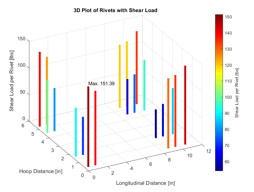
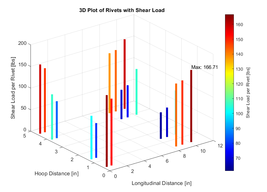
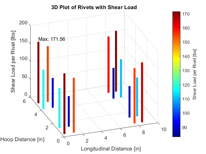
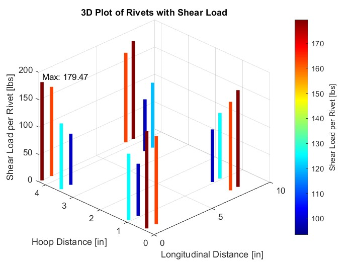
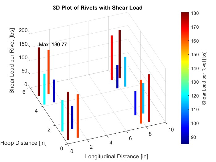
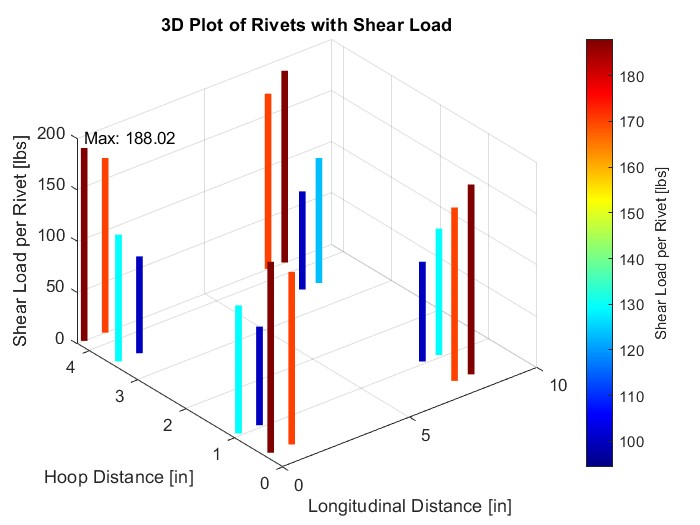
The directional components are combined for every evaluated case; the resulting rivet shear distributions are shown in the figures below.
Shear Loads carried by each rivet in case of maximum L&W values in the FWD region.
Shear Loads carried by each rivet in case of minimum L&W values in the FWD region.
Shear Loads carried by each rivet in case of maximum L&W values, and 1/8” rivet size in the AFT region.
Shear Loads carried by each rivet in case of minimum L&W values, and 1/8” rivet size in the AFT region.
Shear Loads carried by each rivet in case of maximum L&W values, and 5/32” rivet size in the AFT region.
Shear Loads carried by each rivet in case of minimum L&W values, and 5/32” rivet size in the AFT region.
FWD max rivet shear166.71 lbf
AFT max · 5/32 in188.02 lbf
AFT max · 1/8 in179.47 lbf
FWD antenna location:
AFT antenna location:
Bearing Stress at Corner Holes
BEARING CHECKEvaluate the thinnest layer at the corner rivets.
FWD: 0.050 in doubler. AFT: 0.060 in effective fuselage skin/waffle section. Using the thinner participating layer maximizes bearing stress for the local joint check.
In the bearing relation below, is the corner-rivet resultant, is the critical layer thickness, and is conservatively taken as the nominal rivet diameter.
FWD antenna location:
AFT antenna location:
Considering the bearing stress allowable, the margin of safety for
the doubler at the corners can be calculated as below:
FWD antenna location:
AFT antenna location:
The opposite companion layers are thicker than the layers checked above, so their bearing stresses are lower and are covered by comparison.
Maximum resultant shear: 166.71 lbf FWD and 188.02 lbf AFT.
BEARINGPositive margins
Critical corner bearing margins remain positive; the thinner companion layers are passed by comparison.
PASS
Source substantiation supports the AV-265 structural provision.
Direct inertial and aerodynamic antenna loads are non-governing by inspection, while cabin-pressure load redistribution, skin/doubler stresses, rivet loads and corner-hole bearing are substantiated with positive margins.
REFERENCES
Regulatory & Aircraft Load Basis
Federal Aviation Regulations - FAR 23.335, FAR 23.337 and FAR 23.561
Federal Aviation Regulations - FAR 25.303 and FAR 25.365
Aerodynamic Methods
Airfoil Design and Data - Richard Eppler
Fundamentals of Aerodynamics, 3rd Edition - John D. Anderson