INTRODUCTION
Static-strength substantiation of two Storage Pillar installations on the port side of a DHC-8-100. The assessment covers the primary load path, sheet-metal stresses, fastener reactions, attachment loads, and ultimate-strength margins.
The substantiation combines flight and emergency load cases, finite-element analysis, analytical reaction-force checks, material allowables, and fastener/joint capacities.
DESIGN ASSESSMENT
GENERAL LAYOUT
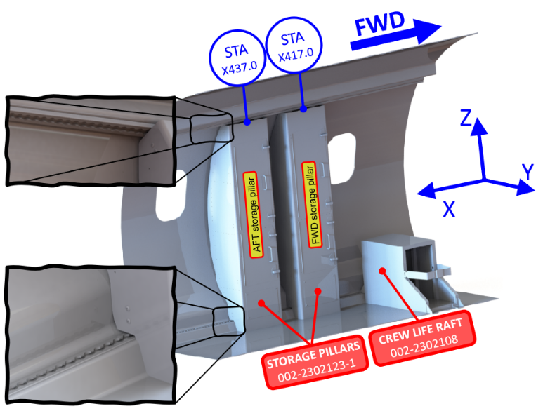
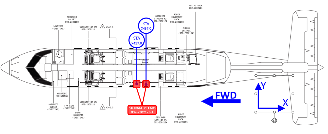
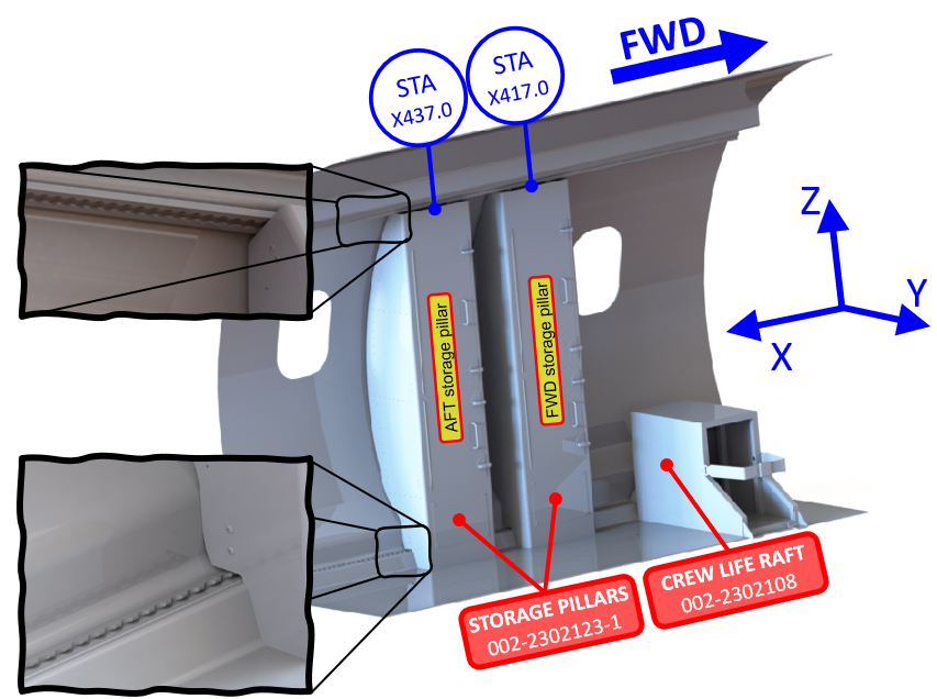
Two geometrically identical Storage Pillars are installed on the port side: the forward pillar at X417 and the aft pillar at X437.
The aft pillar is used for detailed FEM substantiation because both pillars share the same design while the aft installation sees the higher vertical ultimate load. The forward pillar is therefore covered by comparison.
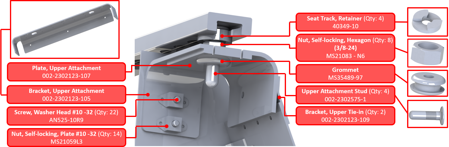
STORAGE PILLAR COMPONENTS
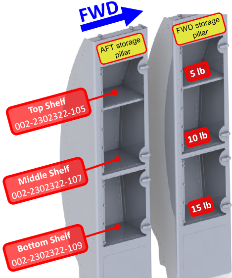
The structural build-up uses 2024-T3 ALCLAD sheet, 6061-T6511 extrusions, and Gillfab 4030 shelf panels. The component and material-property tables below retain the source thicknesses and allowables used for substantiation.
The main structural components of the Storage Pillar along with their material and thickness properties.
| Component | Thickness [in] |
Material |
|---|---|---|
| Shelves | 0.50 | Composite Material; Gillfab 4030-500003FC2T |
| Upper Attachment Bracket | 0.125 | AL. SHEET 2024-T3 ALCLAD AS PER AMS-QQ-A-250/5 |
| Upper Attachment Plate | ||
| Upper Tie-In Bracket | 0.0625 | |
| Lower Attachment Shim | ||
| Lower Attachment Clip | ||
| Lower Tie-In Bracket | ||
| Storage Pillar Panel | ||
| Back Panel | ||
| Stiffener Support Angle | 0.05 | AL. EXT. 6061-T6511 AS PER AMS-QQ-A-200/8 |
| Shelves Support Angles | 0.063 | |
| Lower Attachment C-Channel | 0.125 |
Material properties used in the storage pillar [MMPDS-15- Table 3.2.4.0(c1), Table 3.6.2.0(g)].
CLAD 2024-T3 AL SHEET t=0.063” – 0.128” |
6061-T6511 AL EXT t≤1 |
Direction | Unit | |
|---|---|---|---|---|
| Ftu | 62 | 38 | L | ksi |
| 60 | 37 | LT | ksi | |
| Fty | 45 | 35 | L | ksi |
| 40 | 33 | LT | ksi | |
| Fcy | 37 | 34 | L | ksi |
| 43 | 35 | LT | ksi | |
| Fsu | 38 | 26 | - | ksi |
| Fbru | 101 | 64 | e/D=1.5 | ksi |
| 125 | 82 | e/D=2 | ksi | |
| Fbry | 70 | 54 | e/D=1.5 | ksi |
| 84 | 60 | e/D=2 | ksi | |
| E x103 | 10.50 | 9.90 | - | ksi |
| Ec x103 | 10.70 | 10.10 | - | ksi |
| μ | 0.33 | 0.33 | - | - |
| ρ | 0.1 | 0.098 | - | lbm/in3 |
| G x103 | - | 3.80 | - | ksi |
FASTENERS ALLOWABLES
SUMMARY OF ALLOWABLES
Joint Allowables for the storage pillar station installation.
| P/N | Description | Psu [lbf] |
Ptu [lbf] |
Pbrg [lbf] |
|---|---|---|---|---|
| MS20426AD4 | Solid Rivet 100° countersunk head |
363 | N/R | N/R |
| MS20470AD4 | Solid Rivet Protruded head. |
389 | N/R | 664.2 |
AN525-10R8 AN525-10R9 AN525-10R12 |
Washer Head Screw #10-32 |
2,126 | 2210 | 1496 |
| NAS1834-3-500 | Insert | 1166 | 645 | N/R |
| 002-2302575-1 | Upper Attachment Stud | 341 | N/R | N/R |
| FE200744 | Lower attachment Stud 3/8-24 UNRF |
2,000 | 4,500 | 3844 |
WEIGHTS
Mass properties were derived from the 3D model using the stated material densities. Structural, removed/non-structural, and shelf masses are retained so the FEM reproduces the inertial demand at the correct centers of gravity.
- Aluminum density: 0.1 lbm/in3
- Gillfab 4030 nominal density: 5.787×10⁻⁴ lbm/in3
- Total listed mass: 75.699 lbm
Non-structural hardware and accessories need not be meshed explicitly when their global effect is inertial. Their mass is preserved through NSM / equivalent mass representation on the load-carrying structure.
Structural and Payload Weights of the Storage Pillar and its Equipment along with their CoG locations.
| Component | Volume [in3] |
Weight [lbm] |
CoG [in] | ||
|---|---|---|---|---|---|
| X | Y | Z | |||
| Assembly Structure | 179.3495 | 17.93495 | 5.4981 | -0.4954 | 25.5296 |
| Removed Components✝ | 276.4236 | 27.64236 | N/R | N/R | N/R |
| Top Shelf | 63.8846 | 5.037 | 5.4975 | -0.1586 | 39.9816 |
| Mid Shelf | 78.4662 | 10.0454 | 5.4975 | -0.8514 | 25.4816 |
| Bottom Shelf | 67.8637 | 15.0393 | 5.4052 | -0.0954 | 9.6316 |
| TOTAL | 665.9876 | 75.69901 | |||
STATIC STRESS ANALYSIS
LOAD CASES FORMULATION
The installation is checked against the governing ultimate flight and emergency-landing accelerations summarized below.
Flight-load framework
FAR 25.321 and 25.331–25.351
- General flight loads and symmetric maneuver response
- Flight maneuver envelope and design airspeeds
- Limit maneuver factors, gust and turbulence loads
- Fuel/oil, high-lift, rolling and yaw conditions
Emergency landing
FAR 25.561
- Forward: 9 g
- Downward: 6 g
- Upward: 3 g
- Sideward: 3 g airframe / 4 g seats & attachments
- Rearward: 1.5 g
Governing ultimate load cases applied to the FEM.
| Load Case Number |
Load Factor Direction |
Ultimate Load Value ()[g] |
Governing basis |
|---|---|---|---|
| 1 | Up | 6.24 | Flight |
| 2 | Down | 7.995 | Flight |
| 3 | Outboard | 3.0 | Emergency landing |
| 4 | Inboard | 3.0 | Emergency landing |
| 5 | Forward | 9.0 | Emergency landing |
| - | Aft | 1.5 | Covered conservatively by Forward case |
I separated the directional demands by governing source rather than running duplicate regulatory cases. The vertical conditions are retained from the flight-load basis at 6.24 g upward and 7.995 g downward. Emergency-landing loading governs the 3.0 g outboard, 3.0 g inboard, and 9.0 g forward directions. The 1.5 g aft condition is not modeled separately because the 9 g forward case conservatively envelopes the reverse longitudinal demand. The FEM therefore contains five traceable governing cases without redundant load sets.
FINITE ELEMENT ANALYSIS (FEA)
Only the aft Storage Pillar is modeled. The forward pillar has the same design and a lower vertical ultimate demand, so the aft model provides the conservative substantiation case.
I used the AFT Storage Pillar as the governing structural model because both pillars share the same design while the AFT installation sees the higher vertical ultimate demand. Shelf inertia is introduced at each shelf center of gravity through mass elements and connector spiders; non-structural hardware and accessories are retained through distributed NSM rather than explicit geometry. Loads then flow through the plate-modeled pillar structure and modeled fasteners into the upper and lower attachment studs. CBUSH spiders distribute connection loads around retained structural holes, while bolt connectors carry translation without artificial rotational fixity. Finally, attachment reactions are independently checked with a 3D rigid-body equilibrium model, keeping the global load path efficient, transparent, and auditable.
2D midsurface plates
Thin sheet and extrusion-wall behavior is governed by membrane, bending, and shear response; midsurface plate elements capture those mechanisms efficiently without unnecessary solid-element cost.
Suppress only non-critical geometry
Non-structural holes and small features are removed to prevent artificial local peaks, while fillets and structural attachment holes are retained where local stress gradients are meaningful.
Shelf loads at actual CoG
Shelf weights and rated payloads are represented at their centers of gravity so inertia and overturning moments enter the primary load path without meshing the payload geometry.
Connector-based fasteners
CBUSH / spider arrangements provide controlled joint stiffness and direct reaction extraction while avoiding detailed fastener solids that are unnecessary for global substantiation.
GEOMETRY
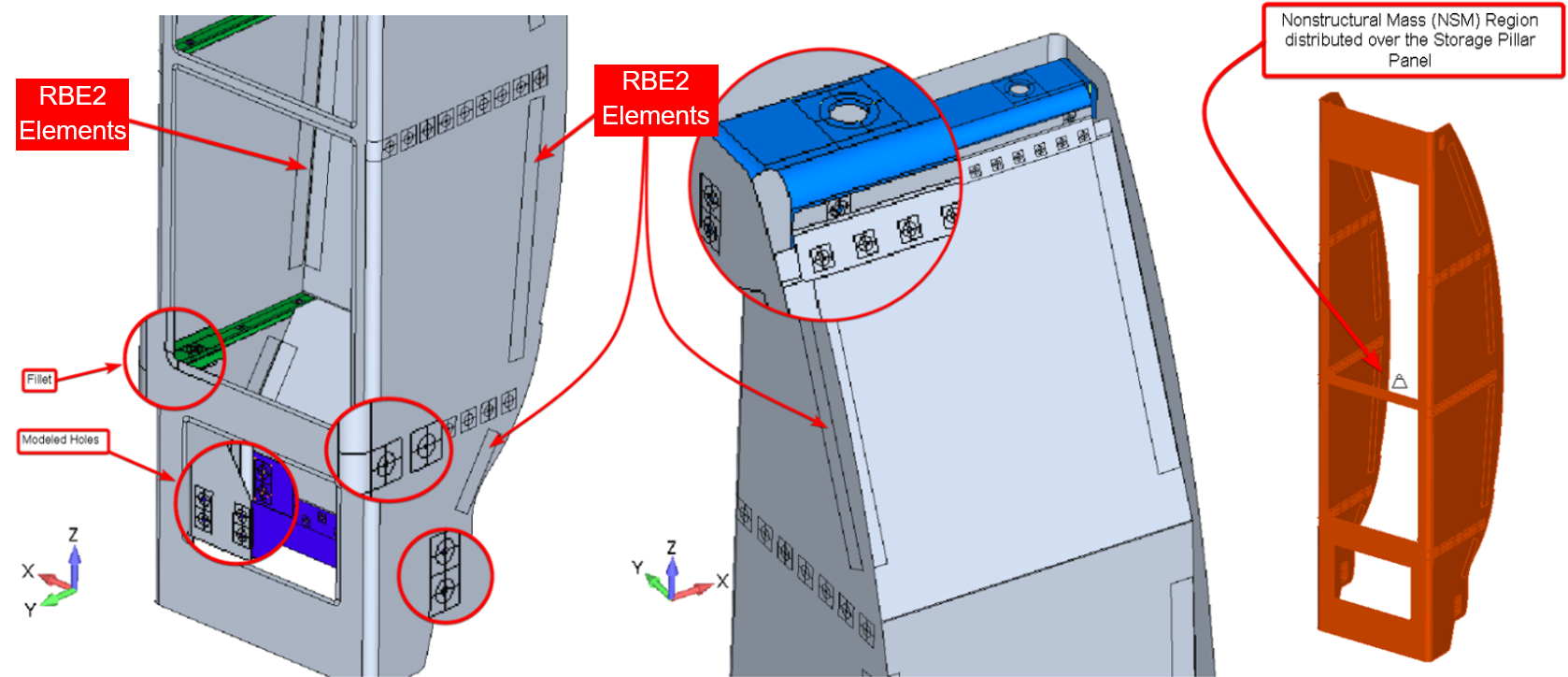
As depicted in the corresponding figure, non-structural components of the storage pillar were excluded from the model to streamline the finite element analysis. These excluded components include, but are not limited to, the storage net and its clips, blocks, doors, locks, hinges, shims, handles, associated accessories, placards, access panels, screws, nuts, and washers. However, their combined equivalent weight (refer to the corresponding table) was considered in the analysis by assigning a Non-Structural Mass (NSM) region distributed across the storage pillar panel.
The geometry of the storage pillar was imported into FEMAP software, where mid-surfaces were extracted, allowing the structure to be modeled using 2D plate elements. This simplification effectively reduces computational complexity while preserving the integrity of the analysis. Non-critical fastener holes, used solely for attaching non-structural components, were covered to avoid unnecessary local stress concentrations that would not impact the primary load path of the structure.
However, to accurately capture stress distributions, the fillets in the geometry were retained, ensuring that areas prone to stress concentration, particularly around curved sections, were modeled with sufficient detail. Fastener holes integral to the connection of structural components were also retained, as they are critical to capturing stress concentrations in these regions. Specifically, stress analysis around these holes ensures compliance with structural integrity requirements, particularly in areas subject to high localized forces.
The rivet holes that join the Storage Pillar Panel to the Back Panel were omitted for simplification. Instead, the common surfaces between these two panels were connected using RBE2 (Rigid Body Elements) to simulate a fully constrained interface. These RBE2 elements were constrained in the translational degrees of freedom (DOFs: Tx, Ty, Tz), allowing for an effective load transfer between the panels without unnecessarily complicating the model.
This approach balances the accuracy of the stress distribution results while ensuring that the computational model remains efficient and representative of the actual loading conditions. The decision to omit non-critical features while preserving key structural elements reflects industry best practices in finite element modeling, particularly for aerospace structural substantiation.
PROPERTIES
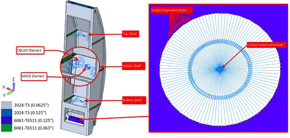
To accurately represent the structural characteristics of the storage pillar, four distinct plate properties were defined in the model, each corresponding to the material and thickness of the various sheets used in the assembly. These properties are illustrated in the corresponding figure, where the sheets were color-coded according to their assigned material properties, enabling easy identification and management within the finite element model.
Distributes load around the hole perimeter and retains a controllable connection stiffness.
Places each inertial load at the shelf CoG and transfers it into the structural attachment pattern.
Transfers shear/tension while avoiding artificial moment fixity at mechanical fastener joints.
A spider configuration of CBUSH elements, with a stiffness of 1x10⁷ lbf/in across all six degrees of freedom (DoFs), was applied at each modeled fastener hole (refer to the corresponding figure). This spider arrangement simulates the fastener behavior and is functionally equivalent to RBE2 elements, but with enhanced flexibility in defining stiffness properties. By adopting CBUSH elements in this way, the model captures the local stiffness around the holes, ensuring a realistic representation of load transfer in these critical areas, which are prone to stress concentration.
To account for the shelf weights and their respective maximum load capacities, mass elements were utilized. These mass elements were positioned at each shelf’s center of gravity (CoG) and were connected to the central nodes of the spider arrangement elements through CBUSH elements with a stiffness of 1x10⁷ lbf/in in all six DoFs. This setup mirrors the functionality of RBE2 elements but with the advantage of customizing the stiffness, allowing for a more precise representation of load distribution throughout the structure.
For the bolts, a similar approach was taken; they were modeled as CBUSH elements with 1x10⁷ lbf/in stiffness in the translational DoFs only, while the rotational DoFs were left free. This approach effectively simulates the actual mechanical behavior of bolts under various loading conditions, reflecting their role in carrying loads while allowing for relative rotational movements in service. These CBUSH elements were introduced between the central independent nodes of each hole’s spider arrangement, ensuring that the bolts' response to external loads is captured accurately. For more specific details regarding the bolt configurations and their placement, refer to the corresponding table, the corresponding table, and the corresponding table.
This method of modeling, incorporating CBUSH elements with tailored stiffness values for both bolts and fasteners, ensures a highly accurate simulation of the complex interactions between structural components. This approach allows for a detailed analysis of stress concentrations, load paths, and potential failure points, providing a robust substantiation of the storage pillar’s structural integrity under various emergency load cases.
CBUSH elements for the MS20426AD4 rivets.
| No | ID | Dhole [in] |
Countersunk Sheet | Non-Countersunk Sheet | ||
|---|---|---|---|---|---|---|
| Material | t [in] | Material | t [in] | |||
| 5 | 775321 | 0.1285 | 2024-T3 ALCLAD | 0.0625 | 6061-T6511 | 0.0630 |
| 6 | 775322 | 0.1285 | 2024-T3 ALCLAD | 0.0625 | 6061-T6511 | 0.0630 |
| 7 | 775323 | 0.1285 | 2024-T3 ALCLAD | 0.0625 | 6061-T6511 | 0.0630 |
| 8 | 775324 | 0.1285 | 2024-T3 ALCLAD | 0.0625 | 6061-T6511 | 0.0630 |
| 9 | 775325 | 0.1285 | 2024-T3 ALCLAD | 0.0625 | 6061-T6511 | 0.0630 |
| 10 | 775326 | 0.1285 | 2024-T3 ALCLAD | 0.0625 | 6061-T6511 | 0.0630 |
| 11 | 775327 | 0.1285 | 2024-T3 ALCLAD | 0.0625 | 6061-T6511 | 0.0630 |
| 12 | 775358 | 0.1285 | 2024-T3 ALCLAD | 0.0625 | 6061-T6511 | 0.0630 |
| 13 | 775359 | 0.1285 | 2024-T3 ALCLAD | 0.0625 | 6061-T6511 | 0.0630 |
| 14 | 775360 | 0.1285 | 2024-T3 ALCLAD | 0.0625 | 6061-T6511 | 0.0630 |
| 15 | 775361 | 0.1285 | 2024-T3 ALCLAD | 0.0625 | 6061-T6511 | 0.0630 |
| 16 | 775362 | 0.1285 | 2024-T3 ALCLAD | 0.0625 | 6061-T6511 | 0.0630 |
| 17 | 775363 | 0.1285 | 2024-T3 ALCLAD | 0.0625 | 6061-T6511 | 0.0630 |
| 18 | 775364 | 0.1285 | 2024-T3 ALCLAD | 0.0625 | 6061-T6511 | 0.0630 |
| 19 | 775328 | 0.1285 | 2024-T3 ALCLAD | 0.0625 | 6061-T6511 | 0.0630 |
| 20 | 775329 | 0.1285 | 2024-T3 ALCLAD | 0.0625 | 6061-T6511 | 0.0630 |
| 21 | 775330 | 0.1285 | 2024-T3 ALCLAD | 0.0625 | 6061-T6511 | 0.0630 |
| 22 | 775331 | 0.1285 | 2024-T3 ALCLAD | 0.0625 | 6061-T6511 | 0.0630 |
| 23 | 775332 | 0.1285 | 2024-T3 ALCLAD | 0.0625 | 6061-T6511 | 0.0630 |
| 24 | 775333 | 0.1285 | 2024-T3 ALCLAD | 0.0625 | 6061-T6511 | 0.0630 |
| 25 | 775334 | 0.1285 | 2024-T3 ALCLAD | 0.0625 | 6061-T6511 | 0.0630 |
| 26 | 775335 | 0.1285 | 2024-T3 ALCLAD | 0.0625 | 6061-T6511 | 0.0630 |
| 27 | 775336 | 0.1285 | 2024-T3 ALCLAD | 0.0625 | 6061-T6511 | 0.0630 |
| 28 | 775349 | 0.1285 | 2024-T3 ALCLAD | 0.0625 | 6061-T6511 | 0.0630 |
| 29 | 775350 | 0.1285 | 2024-T3 ALCLAD | 0.0625 | 6061-T6511 | 0.0630 |
| 30 | 775351 | 0.1285 | 2024-T3 ALCLAD | 0.0625 | 6061-T6511 | 0.0630 |
| 31 | 775352 | 0.1285 | 2024-T3 ALCLAD | 0.0625 | 6061-T6511 | 0.0630 |
| 32 | 775353 | 0.1285 | 2024-T3 ALCLAD | 0.0625 | 6061-T6511 | 0.0630 |
| 33 | 775354 | 0.1285 | 2024-T3 ALCLAD | 0.0625 | 6061-T6511 | 0.0630 |
| 34 | 775355 | 0.1285 | 2024-T3 ALCLAD | 0.0625 | 6061-T6511 | 0.0630 |
| 35 | 775356 | 0.1285 | 2024-T3 ALCLAD | 0.0625 | 6061-T6511 | 0.0630 |
| 36 | 775357 | 0.1285 | 2024-T3 ALCLAD | 0.0625 | 6061-T6511 | 0.0630 |
| 39 | 775337 | 0.1285 | 2024-T3 ALCLAD | 0.0625 | 6061-T6511 | 0.0630 |
| 40 | 775338 | 0.1285 | 2024-T3 ALCLAD | 0.0625 | 6061-T6511 | 0.0630 |
| 41 | 775339 | 0.1285 | 2024-T3 ALCLAD | 0.0625 | 6061-T6511 | 0.0630 |
| 42 | 775340 | 0.1285 | 2024-T3 ALCLAD | 0.0625 | 6061-T6511 | 0.0630 |
| 43 | 775341 | 0.1285 | 2024-T3 ALCLAD | 0.0625 | 6061-T6511 | 0.0630 |
| 44 | 775342 | 0.1285 | 2024-T3 ALCLAD | 0.0625 | 6061-T6511 | 0.0630 |
| 45 | 775343 | 0.1285 | 2024-T3 ALCLAD | 0.0625 | 6061-T6511 | 0.0630 |
| 46 | 775344 | 0.1285 | 2024-T3 ALCLAD | 0.0625 | 6061-T6511 | 0.0630 |
| 47 | 775345 | 0.1285 | 2024-T3 ALCLAD | 0.0625 | 6061-T6511 | 0.0630 |
| 48 | 775346 | 0.1285 | 2024-T3 ALCLAD | 0.0625 | 6061-T6511 | 0.0630 |
| 49 | 775347 | 0.1285 | 2024-T3 ALCLAD | 0.0625 | 6061-T6511 | 0.0630 |
| 50 | 775348 | 0.1285 | 2024-T3 ALCLAD | 0.0625 | 6061-T6511 | 0.0630 |
CBUSH elements for the MS20470AD4 rivets.
| No | ID | Dhole [in] |
First Sheet | Last sheet | ||
|---|---|---|---|---|---|---|
| Material | t [in] | Material | t [in] | |||
| 55 | 775375 | 0.1285 | 2024-T3 ALCLAD | 0.0625 | 6061-T6511 | 0.1250 |
| 56 | 775373 | 0.1285 | 2024-T3 ALCLAD | 0.0625 | 6061-T6511 | 0.1250 |
| 57 | 775376 | 0.1285 | 2024-T3 ALCLAD | 0.0625 | 6061-T6511 | 0.1250 |
| 58 | 775374 | 0.1285 | 2024-T3 ALCLAD | 0.0625 | 6061-T6511 | 0.1250 |
| 59 | 775401 | 0.1285 | 2024-T3 ALCLAD | 0.0625 | 6061-T6511 | 0.1250 |
| 60 | 775405 | 0.1285 | 2024-T3 ALCLAD | 0.0625 | 6061-T6511 | 0.1250 |
| 61 | 775399 | 0.1285 | 2024-T3 ALCLAD | 0.0625 | 6061-T6511 | 0.1250 |
| 62 | 775403 | 0.1285 | 2024-T3 ALCLAD | 0.0625 | 6061-T6511 | 0.1250 |
| 63 | 775379 | 0.1285 | 2024-T3 ALCLAD | 0.0625 | 6061-T6511 | 0.1250 |
| 64 | 775377 | 0.1285 | 2024-T3 ALCLAD | 0.0625 | 6061-T6511 | 0.1250 |
| 65 | 775380 | 0.1285 | 2024-T3 ALCLAD | 0.0625 | 6061-T6511 | 0.1250 |
| 66 | 775378 | 0.1285 | 2024-T3 ALCLAD | 0.0625 | 6061-T6511 | 0.1250 |
| 67 | 775381 | 0.1285 | 2024-T3 ALCLAD | 0.0625 | 6061-T6511 | 0.1250 |
| 68 | 775383 | 0.1285 | 2024-T3 ALCLAD | 0.0625 | 6061-T6511 | 0.1250 |
| 69 | 775413 | 0.1285 | 2024-T3 ALCLAD | 0.0625 | 6061-T6511 | 0.1250 |
| 70 | 775411 | 0.1285 | 2024-T3 ALCLAD | 0.0625 | 6061-T6511 | 0.1250 |
| 71 | 775386 | 0.1285 | 2024-T3 ALCLAD | 0.0625 | 6061-T6511 | 0.1250 |
| 72 | 775388 | 0.1285 | 2024-T3 ALCLAD | 0.0625 | 6061-T6511 | 0.1250 |
| 73 | 775392 | 0.1285 | 2024-T3 ALCLAD | 0.0625 | 6061-T6511 | 0.1250 |
| 74 | 775394 | 0.1285 | 2024-T3 ALCLAD | 0.0625 | 6061-T6511 | 0.1250 |
| 75 | 775398 | 0.1285 | 2024-T3 ALCLAD | 0.0625 | 6061-T6511 | 0.1250 |
| 76 | 775410 | 0.1285 | 2024-T3 ALCLAD | 0.0625 | 6061-T6511 | 0.1250 |
| 77 | 775390 | 0.1285 | 2024-T3 ALCLAD | 0.0625 | 6061-T6511 | 0.1250 |
| 78 | 775408 | 0.1285 | 2024-T3 ALCLAD | 0.0625 | 6061-T6511 | 0.1250 |
| 79 | 775396 | 0.1285 | 2024-T3 ALCLAD | 0.0625 | 6061-T6511 | 0.1250 |
| 109 | 775308 | 0.1285 | 2024-T3 ALCLAD | 0.0625 | 2024-T3 ALCLAD | 0.0625 |
| 110 | 775309 | 0.1285 | 2024-T3 ALCLAD | 0.0625 | 2024-T3 ALCLAD | 0.0625 |
| 111 | 775310 | 0.1285 | 2024-T3 ALCLAD | 0.0625 | 2024-T3 ALCLAD | 0.0625 |
| 112 | 775311 | 0.1285 | 2024-T3 ALCLAD | 0.0625 | 2024-T3 ALCLAD | 0.0625 |
| 113 | 775312 | 0.1285 | 2024-T3 ALCLAD | 0.0625 | 2024-T3 ALCLAD | 0.0625 |
| 114 | 775313 | 0.1285 | 2024-T3 ALCLAD | 0.0625 | 2024-T3 ALCLAD | 0.0625 |
| 115 | 775314 | 0.1285 | 2024-T3 ALCLAD | 0.0625 | 2024-T3 ALCLAD | 0.0625 |
| 116 | 775315 | 0.1285 | 2024-T3 ALCLAD | 0.0625 | 2024-T3 ALCLAD | 0.0625 |
| 117 | 775316 | 0.1285 | 2024-T3 ALCLAD | 0.0625 | 2024-T3 ALCLAD | 0.0625 |
| 118 | 775317 | 0.1285 | 2024-T3 ALCLAD | 0.0625 | 2024-T3 ALCLAD | 0.0625 |
| 119 | 775318 | 0.1285 | 2024-T3 ALCLAD | 0.0625 | 2024-T3 ALCLAD | 0.0625 |
| 120 | 775319 | 0.1285 | 2024-T3 ALCLAD | 0.0625 | 2024-T3 ALCLAD | 0.0625 |
| 121 | 775320 | 0.1285 | 2024-T3 ALCLAD | 0.0625 | 2024-T3 ALCLAD | 0.0625 |
CBUSH elements for the #10-32 AN525-10R bolts.
| No | ID | P/N | Dhole [in] |
First Sheet | Last sheet | ||
|---|---|---|---|---|---|---|---|
| Material | t [in] | Material | t [in] | ||||
| 1 | 775303 | AN525-10R9 | 0.1875 | 2024-T3 ALCLAD | 0.0625 | 2024-T3 ALCLAD | 0.1250 |
| 2 | 775304 | AN525-10R9 | 0.1875 | 2024-T3 ALCLAD | 0.0625 | 2024-T3 ALCLAD | 0.1250 |
| 3 | 775301 | AN525-10R9 | 0.1875 | 2024-T3 ALCLAD | 0.0625 | 2024-T3 ALCLAD | 0.1250 |
| 4 | 775302 | AN525-10R9 | 0.1875 | 2024-T3 ALCLAD | 0.0625 | 2024-T3 ALCLAD | 0.1250 |
| 51 | 775371 | AN525-10R9 | 0.1875 | 2024-T3 ALCLAD | 0.0625 | 2024-T3 ALCLAD | 0.0625 |
| 52 | 775372 | AN525-10R9 | 0.1875 | 2024-T3 ALCLAD | 0.0625 | 2024-T3 ALCLAD | 0.0625 |
| 53 | 775369 | AN525-10R9 | 0.1875 | 2024-T3 ALCLAD | 0.0625 | 2024-T3 ALCLAD | 0.0625 |
| 54 | 775370 | AN525-10R9 | 0.1875 | 2024-T3 ALCLAD | 0.0625 | 2024-T3 ALCLAD | 0.0625 |
| 84 | 775365 | AN525-10R8 | 0.1875 | 2024-T3 ALCLAD | 0.0625 | 2024-T3 ALCLAD | 0.0625 |
| 85 | 775366 | AN525-10R8 | 0.1875 | 2024-T3 ALCLAD | 0.0625 | 2024-T3 ALCLAD | 0.0625 |
| 86 | 775367 | AN525-10R8 | 0.1875 | 2024-T3 ALCLAD | 0.0625 | 2024-T3 ALCLAD | 0.0625 |
| 87 | 775368 | AN525-10R8 | 0.1875 | 2024-T3 ALCLAD | 0.0625 | 2024-T3 ALCLAD | 0.0625 |
| 106 | 775307 | AN525-10R8 | 0.1875 | 2024-T3 ALCLAD | 0.0625 | 2024-T3 ALCLAD | 0.1250 |
| 107 | 775306 | AN525-10R8 | 0.1875 | 2024-T3 ALCLAD | 0.0625 | 2024-T3 ALCLAD | 0.1250 |
| 108 | 775305 | AN525-10R8 | 0.1875 | 2024-T3 ALCLAD | 0.0625 | 2024-T3 ALCLAD | 0.1250 |
LOADS AND CONSTRAINTS
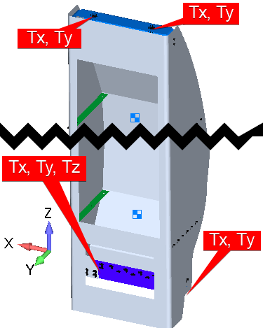
Upper attachmentsTx and Ty restrained.
Forward lower attachmentTx and Ty restrained.
Aft lower attachmentTx, Ty and Tz restrained.
The restraint set follows the directional capability of the attachment system while avoiding unnecessary fixity. This preserves the intended load path and reduces the risk of artificially stiffening the pillar.

Case: (1) (2) (3) (4) (5)
The Tx (translation along the x-axis) and Ty (translation along the y-axis) DoFs were restrained at both upper attachment points to prevent longitudinal and lateral displacements.
The Tx and Ty DoFs were similarly restrained at the forward lower attachment to maintain consistency in preventing longitudinal and lateral movements.
At the aft lower attachment, the Tx, Ty, and Tz (translation along the z-axis) DoFs were restrained, adding an additional constraint to prevent vertical movement, thus ensuring stability at the lower end of the structure under forward loading conditions.
MESH
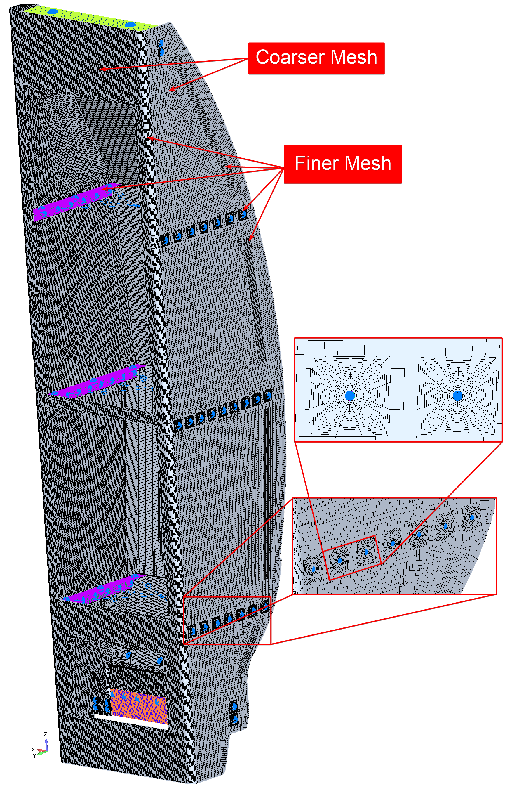
The finite element (FE) model is comprised of 441,491 2D elements, primarily consisting of QUAD 4-noded elements. This element type is well-suited for accurately capturing the structural behavior of the storage pillar, particularly in regions subject to complex loading and stress distributions.
97.32% QUAD4 elements with TRI3 usage limited to 0.46%, minimizing artificial stiffness in critical stress regions.
Fine mesh at fillets, holes and attachment points; coarser mesh in low-gradient regions. Pads and washers improve hole-region load introduction and result stability.
The distribution of element types within the model reflects a deliberate approach to ensure both computational efficiency and accuracy. 97.32% of the elements used are QUAD 4-noded elements, while only 0.46% are TRI 3-noded elements. The limited use of TRI elements is intentional, as these elements tend to exhibit artificial stiffness, especially in regions with high stress concentrations. Their application was minimized to avoid compromising the accuracy of the stress analysis, particularly in critical areas where precision is paramount.
A fine mesh was applied in regions of high stress, such as around fillets and attachment points, where accurate stress distribution is essential to assess the structure's integrity. The finer mesh ensures that stress gradients are well captured, particularly around areas with geometric discontinuities or potential stress risers. In contrast, a coarser mesh was used in less critical regions where stress variations are minimal, optimizing the computational performance of the model without sacrificing accuracy where it matters most.
Pads and Washers were implemented around each modeled hole, to ensure the results accuracy in those regions.
ANALYSIS
A static stress analysis (SESTATIC - SOL 101) was selected as the method for evaluating the structural performance of the storage pillar installation, utilizing SIMCENTER NASTRAN as the computational analysis program. This analysis type is well-suited for assessing the response of the structure under static loading conditions, ensuring that the design meets the necessary strength and safety criteria required for certification.
In this model, the units for weight, density, and acceleration were defined in pound mass (lbm), pound mass per cubic inch (lbm/in³), and inches per second squared (in/s²), respectively. Given this unit system, the WTMASS parameter was activated to perform the necessary conversions and corrections within the solver. This parameter ensures that the outputs for force and stress are provided in the correct units, specifically pounds-force (lbf) for force and pounds per square inch (psi) for stress.
By enabling the WTMASS parameter, any discrepancies between mass and force units are accounted for, ensuring that the results accurately reflect the real-world conditions the storage pillar will experience. This approach guarantees that the static stress analysis produces reliable and precise results, allowing for informed decisions regarding the structural integrity of the modification and ensuring compliance with all regulatory and safety standards.
Linear static analysis is appropriate for the defined inertial load cases and global strength substantiation.
Converts the lbm–in–s unit system so solver force and stress output is interpreted consistently as lbf and psi.
FEA RESULTS
FEA VALIDATION
The reaction forces at the attachment points were extracted and summarized in the corresponding table.
Attachment reactions from the FEM are cross-checked using a simplified 3D rigid-body equilibrium model for the 9 g forward and 3 g inboard cases. Agreement is used as a global sanity check before stress and fastener assessment.
Reaction forces components [lbf] for all cases as extracted from the FE model.
| Node | Location | FWD | INBOARD | OUTBOARD | DOWN | UP | ||||||||||
|---|---|---|---|---|---|---|---|---|---|---|---|---|---|---|---|---|
| Rx | Ry | Rz | Rx | Ry | Rz | Rx | Ry | Rz | Rx | Ry | Rz | Rx | Ry | Rz | ||
| 3548 | LOWER - AFT | 205.84 | 61.70 | 0.00 | 5.62 | -63.88 | 0.00 | -5.62 | 63.88 | 0.00 | 168.85 | -32.35 | 597.00 | -131.78 | 25.25 | -465.95 |
| 3761 | LOWER - FWD | 178.95 | -61.70 | 0.00 | -5.62 | -64.38 | 0.00 | 5.62 | 64.38 | 0.00 | -228.42 | 32.99 | 0.00 | 178.28 | -25.75 | 0.00 |
| 7880 | UPPER - AFT | 144.57 | 24.32 | 0.00 | 62.52 | -47.63 | 0.00 | -62.52 | 47.63 | 0.00 | 42.72 | 68.27 | 0.00 | -33.34 | -53.29 | 0.00 |
| 8007 | UPPER - FWD | 142.69 | -24.32 | 0.00 | -62.52 | -48.13 | 0.00 | 62.52 | 48.13 | 0.00 | 16.86 | -68.92 | 0.00 | -13.16 | 53.79 | 0.00 |
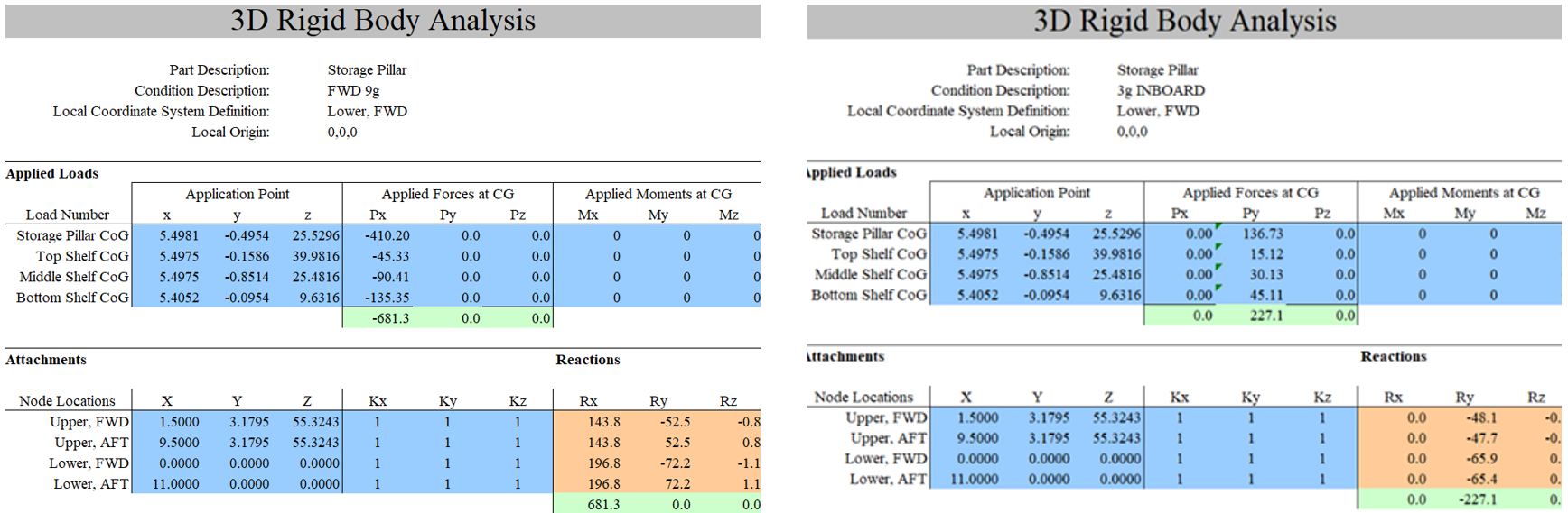
To verify the FE model, the 9 g FORWARD case is examined in an analytical method. The problem is simplified as follows. It is assumed that each shelf weight and its corresponding maximum load capacity as point masses located at their CoG. The structural and non-structural weights of the storage pillar are combined into one point mass located at the storage pillar’s CoG. Based on the corresponding table, the total weight of these components are as follows:
Top Shelf weight, wtop = 5.037 lbm = 0.1566 slug
Middle Shelf weight, wmiddle = 10.0454 lbm = 0.3122 slug
Bottom Shelf weight, wbottom = 15.0393 lbm = 0.4674 slug
Combined Storage Pillar weight, wp = 17.935+27.6424 = 45.5773 lbm = 1.4166 slug
Hence, the total applied force at the CoG of each component can be calculated as follows:
Top Shelf force, Ftop = 0.1566 slug x -9 x 32.174049 ft/s2 = -45.33 lbf
Middle Shelf force, Fmiddle = 10.0454 slug x -9 x 32.174049 ft/s2 = -90.41lbf
Bottom Shelf force, Fbottom = 15.0393 slug x -9 x 32.174049 ft/s2 = -135.35 lbf
Combined Storage Pillar force, Fp = 45.5773 slug x -9 x 32.174049 ft/s2 = -410.20 lbf
Considering the coordinates of the upper and lower attachments, and by utilizing the “3D Rigid Body Analysis”. The reaction force along the x-direction at the attachment points are summarized in the corresponding table. The output from this analysis is shown in the corresponding figure. Similar calculations have been done for the 3 g inboard case to compare the reaction force along the y-direction, and the results are summarized in the same Table.
Reaction force comparison from the FE model and from the 3D Rigid Body Analysis.
| Node | Location | FWD | INBOARD | ||
|---|---|---|---|---|---|
| Rx | Ry | ||||
| FE | 3D-RBA | FE | 3D-RBA | ||
| 3548 | LOWER - AFT | 205.84 | 196.85 | -63.88 | -65.37 |
| 3761 | LOWER - FWD | 178.95 | 196.85 | -64.38 | -65.92 |
| 7880 | UPPER - AFT | 144.57 | 143.8 | -47.63 | -47.71 |
| 8007 | UPPER - FWD | 142.69 | 143.8 | -48.13 | -48.11 |
SKIN PANELS ASSESSMENT
Principal stresses are reviewed on both plate faces for every load case. Tensile demand is compared with the material ultimate tensile allowable, while compressive demand is compared with the compressive yield allowable; the governing values are summarized in the following table.
Identify the source of the peak first. The source report flags very high principal stresses when they occur directly beside retained fastener holes or rigid-body connections, where the local FEM response can be dominated by connection idealization and geometric discontinuity. Those peaks are kept visible in the global result review for conservatism, but the surrounding stress field is also assessed after excluding only the specifically identified artificial peak elements. No numerical screening threshold is defined in the source; the distinction is made from the peak location and its relationship to the modeled hole / rigid element. Material margins are then based on the representative surrounding-field stresses while the original maxima remain documented for traceability.
Maximum and Minimum Principal Stresses in the storage pillar assembly, sorted by material type. The highlighted cells represent the maximum tensile and compressive principal stresses for each material.
| 2024-T3 | |||||||||||||
|---|---|---|---|---|---|---|---|---|---|---|---|---|---|
| Case 5: 9 g FORWARD | Case 4: 3 g INBOARD | Case 3: 3 g OUTBOARD | Case 2: 7.995 g DOWN | Case 1: 6.24 g UP | MAX T [ksi] |
MAX C [ksi] |
|||||||
Major Principal Stress [ksi] |
Minor Principal Stress [ksi] |
Major Principal Stress [ksi] |
Minor Principal Stress [ksi] |
Major Principal Stress [ksi] |
Minor Principal Stress [ksi] |
Major Principal Stress [ksi] |
Minor Principal Stress [ksi] |
Major Principal Stress [ksi] |
Minor Principal Stress [ksi] |
||||
| TOP | T | 98.90 | 82.72 | 29.32 | 10.94 | 30.08 | 11.26 | 65.75 | 24.24 | 22.26 | 8.25 | 122.99 | 114.06 |
| C | 62.41 | 114.06 | 11.26 | 30.08 | 10.94 | 29.32 | 10.57 | 28.52 | 18.92 | 51.32 | |||
| BOT | T | 122.99 | 60.39 | 29.87 | 11.15 | 29.49 | 11.05 | 26.47 | 8.49 | 58.85 | 20.76 | ||
| C | 83.29 | 100.41 | 11.05 | 29.49 | 11.15 | 29.87 | 26.60 | 75.40 | 6.63 | 20.66 | |||
| 6061-T6 | |||||||||||||
| Case 5: 9 g FORWARD | Case 4: 3 g INBOARD | Case 3: 3 g OUTBOARD | Case 2: 7.995 g DOWN | Case 1: 6.24 g UP | MAX T [ksi] |
MAX C [ksi] |
|||||||
Major Principal Stress [ksi] |
Minor Principal Stress [ksi] |
Major Principal Stress [ksi] |
Minor Principal Stress [ksi] |
Major Principal Stress [ksi] |
Minor Principal Stress [ksi] |
Major Principal Stress [ksi] |
Minor Principal Stress [ksi] |
Major Principal Stress [ksi] |
Minor Principal Stress [ksi] |
||||
| TOP | T | 99.72 | 33.79 | 5.58 | 1.85 | 6.24 | 2.15 | 16.15 | 4.32 | 51.73 | 21.01 | 99.72 | 79.41 |
| C | 25.04 | 66.70 | 2.15 | 6.24 | 1.85 | 5.58 | 26.92 | 66.27 | 3.37 | 12.61 | |||
| BOT | T | 68.48 | 25.45 | 5.74 | 1.67 | 5.46 | 1.74 | 65.11 | 26.45 | 15.85 | 6.58 | ||
| C | 27.73 | 79.41 | 1.74 | 5.46 | 1.67 | 5.74 | 8.43 | 20.31 | 20.65 | 50.82 | |||
AL 2024-T3
As shown in the corresponding table, the Maximum Tensile Principal Stress in 2024-T3 sheets reach 122,985.4 psi under loading Case #5 (9 g FORWARD) at the bottom side of the element. In addition, the Maximum Compression Principal Stress in 2024-T3 sheets reach 114,057.2 psi under the same loading Case at the top side of the element.
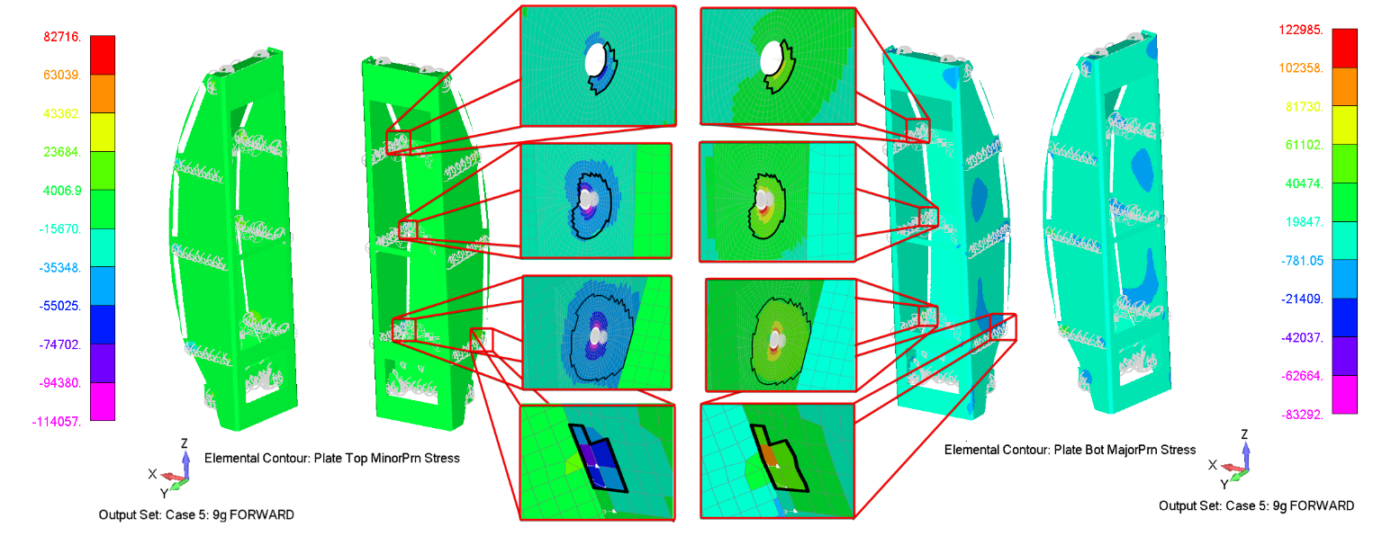
As illustrated in the corresponding figure, these elements exhibit high Tensile and/or Compression Principal Stress because they are either close to a hole or to a rigid body (RBE2) element. The stress values at such areas are generally regarded as irregular and are commonly treated with caution or omitted from overall failure assessments, as they do not represent the average stress distribution across the component. It is noteworthy that there are more elements exist in such areas within the AL2024-T3 sheets, but we will take them into consideration in the assessment for conservatism to ensure extra margin of safety.
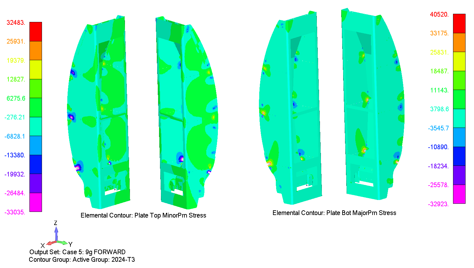
Excluding the high-stress elements shown in the corresponding figure, the resulted Minimum and Maximum Principal Stresses contours for the rest of elements is shown in the corresponding figure. Based on the corresponding figure, the Maximum Tensile and Compression Principal Stress values in the AL 2024-T3 sheets are 40,520 psi and 33,035 psi, respectively. Based on the corresponding table, the AL 2024-T3 sheet has an allowable ultimate tensile strength (ftu) and allowable yield compressive strength (fcy) of 62 and 37 ksi, respectively. The minimum margin of safety will be the lowest value between the tensile load MST and the compressive load MSC. These margins of safety can be expressed as below:
AL 6061-T6511
As shown in the corresponding table, the Maximum Tensile Principal Stress in 6061-T6511 sheets reach 99,724.18 psi under loading Case #5 (9 g FORWARD) at the top side of the element. In addition, the Maximum Compression Principal Stress in 6061-T6511 sheets reach 79,406.67 psi under the same loading Case at the bottom side of the element.
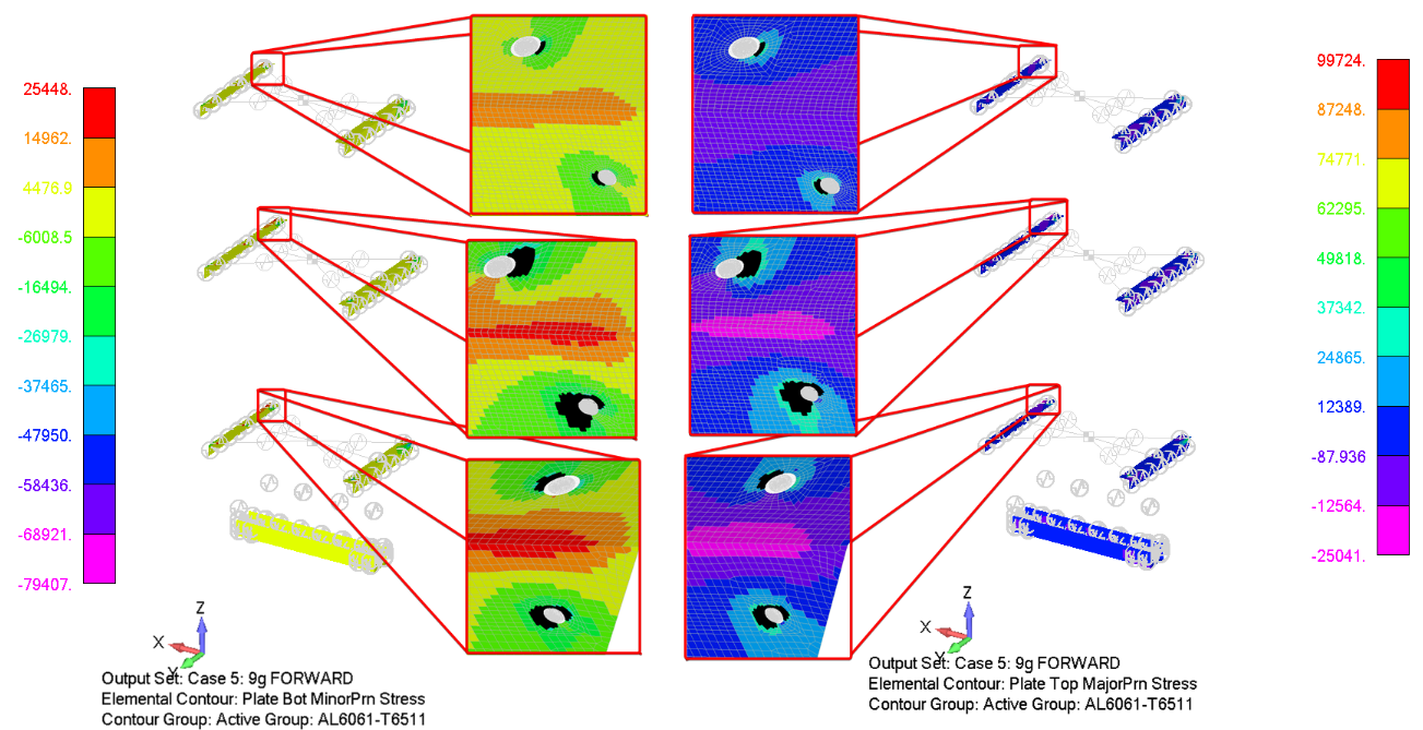
As illustrated in the corresponding figure, these elements exhibit high Tensile and/or Compression Principal Stress because they are close to a hole. The stress values at such areas are generally regarded as irregular and are commonly treated with caution or omitted from overall failure assessments, as they do not represent the average stress distribution across the component. It is noteworthy that there are more elements exist in such areas within the AL6061-T6511 sheets, but we will take them into consideration in the assessment for conservatism to ensure extra margin of safety.
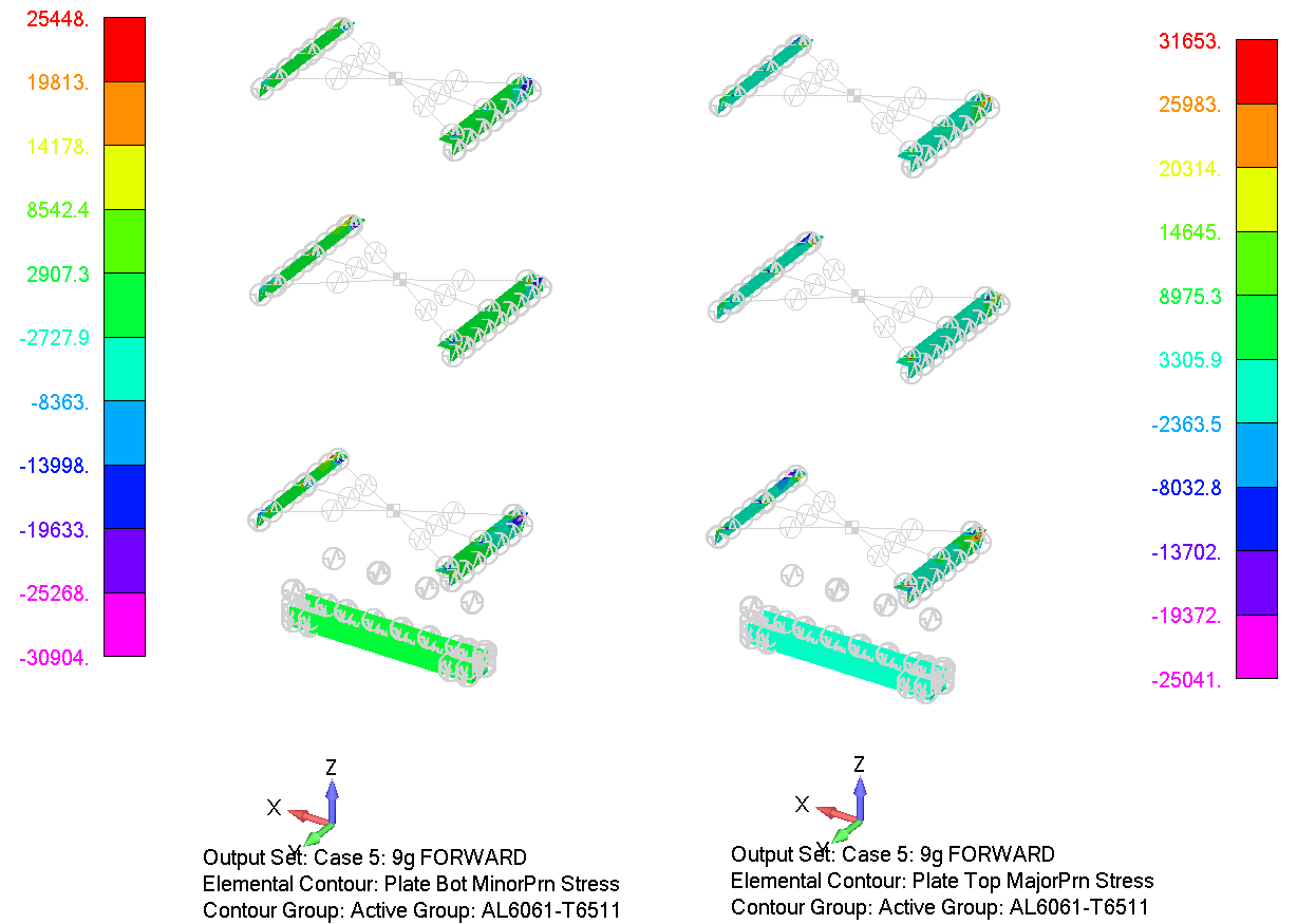
Excluding the high-stress elements shown in the corresponding figure, the resulted Minimum and Maximum Principal Stresses contours for the rest of elements is shown in the corresponding figure. Based on the corresponding figure, the Maximum Tensile and Compression Principal Stress values in the AL6061-T6511 sheets are 31,653 psi and 30,904 psi, respectively. Based on the corresponding table, the AL6061-T6511 sheet has an allowable ultimate tensile strength (ftu) and allowable yield compressive strength (fcy) of 38 and 34 ksi, respectively. The minimum margin of safety will be the lowest value between the tensile load MST and the compressive load MSC. These margins of safety can be expressed as below:
REACTION FORCES ASSESSMENT
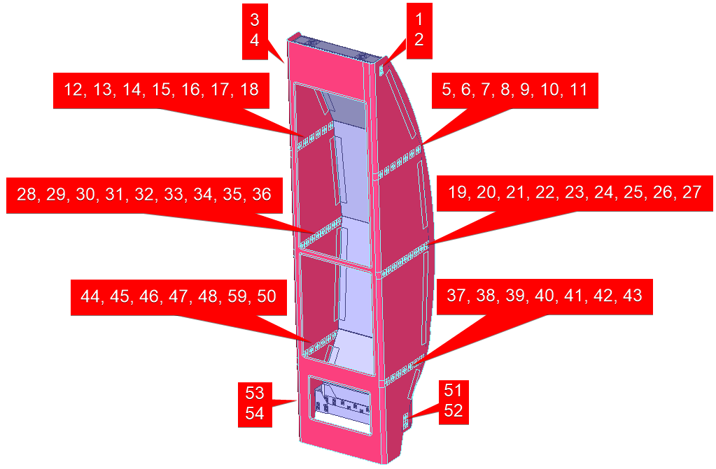
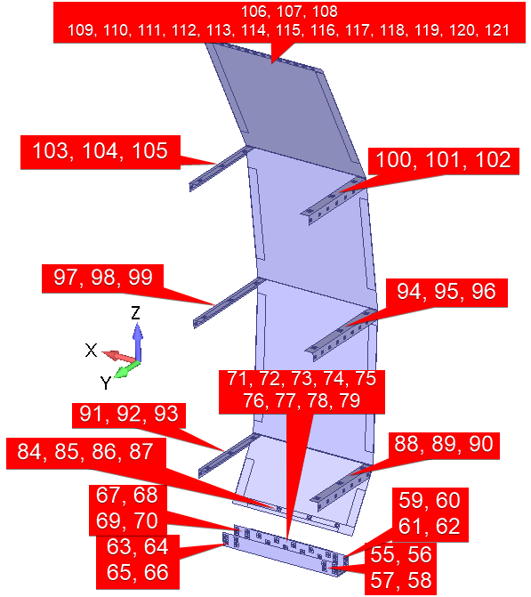
Each modeled fastener is uniquely identified so connector reactions can be extracted by load case and checked directly against the applicable fastener or joint allowable.
REACTION FORCES AT MS20470AD4 RIVETS.
the corresponding table lists the reaction forces components carried by MS20470AD4 rivets in all cases. The highlighted cells identify the shear-force components.
Reaction forces components [lbf] at the MS20470AD4 rivets for all cases. The highlighted cells identify the shear components.
| No | ID | Case 5: 9 g FORWARD |
Case 4: 3 g INBOARD |
Case 3: 3 g OUTBOARD |
Case 2: 7.995 g DOWN |
Case 1: 6.24 g UP |
||||||||||
|---|---|---|---|---|---|---|---|---|---|---|---|---|---|---|---|---|
| X | Y | Z | X | Y | Z | X | Y | Z | X | Y | Z | X | Y | Z | ||
| 55 | 775375 | 21.81 | 0.07 | -5.98 | -21.81 | -0.07 | 5.98 | -18.94 | 1.01 | 5.24 | 14.78 | -0.79 | -4.09 | 21.81 | 0.07 | -5.98 |
| 56 | 775373 | -21.58 | 4.83 | 26.31 | 21.58 | -4.83 | -26.31 | 4.17 | -1.56 | -21.66 | -3.25 | 1.21 | 16.91 | -21.58 | 4.83 | 26.31 |
| 57 | 775376 | 41.37 | -7.35 | -6.25 | -41.37 | 7.35 | 6.25 | -11.99 | 2.56 | 2.92 | 9.36 | -2.00 | -2.28 | 41.37 | -7.35 | -6.25 |
| 58 | 775374 | -30.50 | 31.77 | 6.10 | 30.50 | -31.77 | -6.10 | 23.38 | -14.18 | -12.99 | -18.25 | 11.07 | 10.13 | -30.50 | 31.77 | 6.10 |
| 59 | 775401 | -9.69 | 1.26 | 0.88 | 9.69 | -1.26 | -0.88 | 7.66 | 2.39 | 6.84 | -5.98 | -1.87 | -5.34 | -9.69 | 1.26 | 0.88 |
| 60 | 775405 | 34.54 | 2.76 | -21.90 | -34.54 | -2.76 | 21.90 | -9.14 | 1.96 | -6.51 | 7.14 | -1.53 | 5.08 | 34.54 | 2.76 | -21.90 |
| 61 | 775399 | -27.23 | -4.06 | -0.89 | 27.23 | 4.06 | 0.89 | 24.62 | 0.51 | 7.36 | -19.22 | -0.40 | -5.74 | -27.23 | -4.06 | -0.89 |
| 62 | 775403 | 49.26 | 32.74 | -3.26 | -49.26 | -32.74 | 3.26 | 0.25 | -19.04 | -10.39 | -0.20 | 14.86 | 8.11 | 49.26 | 32.74 | -3.26 |
| 63 | 775379 | 21.58 | 5.39 | 25.19 | -21.58 | -5.39 | -25.19 | -19.73 | -45.56 | -176.25 | 15.40 | 35.56 | 137.56 | 21.58 | 5.39 | 25.19 |
| 64 | 775377 | -21.45 | 0.15 | -5.87 | 21.45 | -0.15 | 5.87 | 99.08 | 1.17 | 34.71 | -77.33 | -0.91 | -27.09 | -21.45 | 0.15 | -5.87 |
| 65 | 775380 | 30.55 | 31.15 | 6.43 | -30.55 | -31.15 | -6.43 | -71.66 | 7.33 | -109.08 | 55.93 | -5.72 | 85.14 | 30.55 | 31.15 | 6.43 |
| 66 | 775378 | -41.64 | -7.38 | -5.74 | 41.64 | 7.38 | 5.74 | -10.41 | 9.19 | 45.73 | 8.12 | -7.18 | -35.69 | -41.64 | -7.38 | -5.74 |
| 67 | 775381 | -33.27 | 2.67 | -21.39 | 33.27 | -2.67 | 21.39 | -78.12 | 63.88 | -185.96 | 60.97 | -49.86 | 145.14 | -33.27 | 2.67 | -21.39 |
| 68 | 775383 | 9.87 | 1.87 | 1.26 | -9.87 | -1.87 | -1.26 | 44.37 | 13.90 | -8.97 | -34.63 | -10.85 | 7.00 | 9.87 | 1.87 | 1.26 |
| 69 | 775413 | -47.89 | 32.56 | -3.29 | 47.89 | -32.56 | 3.29 | -90.15 | -21.42 | -108.53 | 70.36 | 16.72 | 84.71 | -47.89 | 32.56 | -3.29 |
| 70 | 775411 | 27.34 | -4.71 | -0.29 | -27.34 | 4.71 | 0.29 | -5.20 | -8.57 | -4.60 | 4.06 | 6.69 | 3.59 | 27.34 | -4.71 | -0.29 |
| 71 | 775385 | 2.22 | 2.50 | 1.94 | -2.22 | -2.50 | -1.94 | 16.37 | 6.81 | -10.23 | -12.78 | -5.32 | 7.98 | 2.22 | 2.50 | 1.94 |
| 72 | 775387 | 3.57 | 2.54 | -1.09 | -3.57 | -2.54 | 1.09 | 35.70 | 1.91 | -11.53 | -27.86 | -1.49 | 9.00 | 3.57 | 2.54 | -1.09 |
| 73 | 775391 | -0.29 | 2.41 | -1.40 | 0.29 | -2.41 | 1.40 | 24.17 | 2.36 | -3.74 | -18.86 | -1.84 | 2.92 | -0.29 | 2.41 | -1.40 |
| 74 | 775393 | -3.89 | 2.67 | -0.68 | 3.89 | -2.67 | 0.68 | 23.62 | 2.46 | 0.98 | -18.44 | -1.92 | -0.76 | -3.89 | 2.67 | -0.68 |
| 75 | 775397 | -1.40 | 2.35 | 1.85 | 1.40 | -2.35 | -1.85 | 15.24 | -0.41 | -3.76 | -11.89 | 0.32 | 2.93 | -1.40 | 2.35 | 1.85 |
| 76 | 775409 | 7.49 | -2.66 | 3.05 | -7.49 | 2.66 | -3.05 | 16.50 | -3.74 | -12.85 | -12.88 | 2.92 | 10.03 | 7.49 | -2.66 | 3.05 |
| 77 | 775389 | 2.39 | -2.43 | 0.39 | -2.39 | 2.43 | -0.39 | 5.25 | -0.93 | -7.64 | -4.09 | 0.73 | 5.97 | 2.39 | -2.43 | 0.39 |
| 78 | 775407 | -4.43 | -2.56 | 0.70 | 4.43 | 2.56 | -0.70 | 12.38 | -1.52 | -0.90 | -9.66 | 1.19 | 0.70 | -4.43 | -2.56 | 0.70 |
| 79 | 775395 | -8.74 | -2.55 | 3.93 | 8.74 | 2.55 | -3.93 | 22.17 | -1.17 | 0.85 | -17.30 | 0.91 | -0.67 | -8.74 | -2.55 | 3.93 |
| 109 | 775308 | 6.57 | -3.22 | -10.54 | -6.57 | 3.22 | 10.54 | 13.42 | -3.41 | -11.95 | -10.47 | 2.66 | 9.33 | 6.57 | -3.22 | -10.54 |
| 110 | 775309 | 1.90 | 1.25 | 1.54 | -1.90 | -1.25 | -1.54 | -5.12 | -0.62 | -3.71 | 4.00 | 0.48 | 2.90 | 1.90 | 1.25 | 1.54 |
| 111 | 775310 | -3.26 | 0.46 | 1.02 | 3.26 | -0.46 | -1.02 | 4.74 | 1.50 | 3.30 | -3.70 | -1.17 | -2.58 | -3.26 | 0.46 | 1.02 |
| 112 | 775311 | 3.68 | -0.33 | -0.99 | -3.68 | 0.33 | 0.99 | -4.20 | -0.47 | -1.38 | 3.28 | 0.37 | 1.07 | 3.68 | -0.33 | -0.99 |
| 113 | 775312 | -4.09 | 0.43 | 1.10 | 4.09 | -0.43 | -1.10 | 3.80 | -0.15 | -0.12 | -2.97 | 0.12 | 0.10 | -4.09 | 0.43 | 1.10 |
| 114 | 775313 | -3.92 | 1.11 | 2.83 | 3.92 | -1.11 | -2.83 | 3.66 | -0.85 | -1.69 | -2.86 | 0.67 | 1.32 | -3.92 | 1.11 | 2.83 |
| 115 | 775314 | 0.03 | 2.31 | 6.11 | -0.03 | -2.31 | -6.11 | 3.53 | -0.05 | 0.26 | -2.75 | 0.04 | -0.20 | 0.03 | 2.31 | 6.11 |
| 116 | 775315 | -3.97 | -1.11 | -2.83 | 3.97 | 1.11 | 2.83 | -4.51 | -0.85 | -2.25 | 3.52 | 0.66 | 1.76 | -3.97 | -1.11 | -2.83 |
| 117 | 775316 | 4.14 | 0.43 | 1.10 | -4.14 | -0.43 | -1.10 | 4.31 | 0.45 | 1.22 | -3.37 | -0.35 | -0.95 | 4.14 | 0.43 | 1.10 |
| 118 | 775317 | 3.72 | 0.33 | 0.99 | -3.72 | -0.33 | -0.99 | 3.83 | 0.17 | 0.60 | -2.99 | -0.13 | -0.47 | 3.72 | 0.33 | 0.99 |
| 119 | 775318 | 3.29 | 0.47 | 1.04 | -3.29 | -0.47 | -1.04 | 3.34 | 0.03 | 0.04 | -2.61 | -0.02 | -0.03 | 3.29 | 0.47 | 1.04 |
| 120 | 775319 | 1.89 | -1.23 | -1.49 | -1.89 | 1.23 | 1.49 | 2.55 | -0.87 | -0.88 | -1.99 | 0.68 | 0.68 | 1.89 | -1.23 | -1.49 |
| 121 | 775320 | -6.70 | -3.24 | -10.55 | 6.70 | 3.24 | 10.55 | -1.22 | 0.16 | -1.79 | 0.95 | -0.12 | 1.39 | -6.70 | -3.24 | -10.55 |
The resultant shear forces carried by the MS20470AD4 rivets are listed in the corresponding table, and it is calculated using .
Resultant shear force [lbf] calculated from the source reaction table.
| No | ID | Case 5: 9 g FORWARD |
Case 4: 3 g INBOARD |
Case 3: 3 g OUTBOARD |
Case 2: 7.995 g DOWN |
Case 1: 6.24 g UP |
|---|---|---|---|---|---|---|
| 55 | 775375 | 22.62 | 22.62 | 19.65 | 15.34 | 22.62 |
| 55 | 775375 | 34.03 | 34.03 | 22.06 | 17.22 | 34.03 |
| 56 | 775373 | 41.84 | 41.84 | 12.34 | 9.63 | 41.84 |
| 57 | 775376 | 31.10 | 31.10 | 26.75 | 20.88 | 31.10 |
| 58 | 775374 | 9.73 | 9.73 | 10.26 | 8.01 | 9.73 |
| 59 | 775401 | 40.90 | 40.90 | 11.22 | 8.76 | 40.90 |
| 60 | 775405 | 27.25 | 27.25 | 25.70 | 20.06 | 27.25 |
| 61 | 775399 | 49.37 | 49.37 | 10.40 | 8.11 | 49.37 |
| 62 | 775403 | 33.17 | 33.17 | 177.35 | 138.42 | 33.17 |
| 63 | 775379 | 22.24 | 22.24 | 104.98 | 81.94 | 22.24 |
| 64 | 775377 | 31.22 | 31.22 | 130.51 | 101.86 | 31.22 |
| 65 | 775380 | 42.03 | 42.03 | 46.90 | 36.61 | 42.03 |
| 66 | 775378 | 39.55 | 39.55 | 201.71 | 157.43 | 39.55 |
| 67 | 775381 | 9.95 | 9.95 | 45.27 | 35.33 | 9.95 |
| 68 | 775383 | 48.00 | 48.00 | 141.09 | 110.12 | 48.00 |
| 69 | 775413 | 27.34 | 27.34 | 6.94 | 5.42 | 27.34 |
| 70 | 775411 | 2.95 | 2.95 | 19.30 | 15.06 | 2.95 |
| 71 | 775385 | 3.73 | 3.73 | 37.52 | 29.28 | 3.73 |
| 72 | 775387 | 1.43 | 1.43 | 24.45 | 19.09 | 1.43 |
| 73 | 775391 | 3.95 | 3.95 | 23.64 | 18.45 | 3.95 |
| 74 | 775393 | 2.32 | 2.32 | 15.69 | 12.25 | 2.32 |
| 75 | 775397 | 8.09 | 8.09 | 20.91 | 16.32 | 8.09 |
| 76 | 775409 | 2.42 | 2.42 | 9.27 | 7.24 | 2.42 |
| 77 | 775389 | 4.48 | 4.48 | 12.42 | 9.69 | 4.48 |
| 78 | 775407 | 9.58 | 9.58 | 22.19 | 17.32 | 9.58 |
| 79 | 775395 | 12.41 | 12.41 | 17.97 | 14.02 | 12.41 |
| 109 | 775308 | 2.45 | 2.45 | 6.33 | 4.94 | 2.45 |
| 110 | 775309 | 3.42 | 3.42 | 5.78 | 4.51 | 3.42 |
| 111 | 775310 | 3.81 | 3.81 | 4.42 | 3.45 | 3.81 |
| 112 | 775311 | 4.23 | 4.23 | 3.81 | 2.97 | 4.23 |
| 113 | 775312 | 4.83 | 4.83 | 4.03 | 3.15 | 4.83 |
| 114 | 775313 | 6.11 | 6.11 | 3.54 | 2.76 | 6.11 |
| 115 | 775314 | 4.88 | 4.88 | 5.04 | 3.93 | 4.88 |
| 116 | 775315 | 4.28 | 4.28 | 4.48 | 3.50 | 4.28 |
| 117 | 775316 | 3.85 | 3.85 | 3.88 | 3.02 | 3.85 |
| 118 | 775317 | 3.45 | 3.45 | 3.34 | 2.61 | 3.45 |
| 119 | 775318 | 2.41 | 2.41 | 2.70 | 2.11 | 2.41 |
| 120 | 775319 | 12.50 | 12.50 | 2.16 | 1.69 | 12.50 |
| 121 | 775320 | 22.62 | 22.62 | 19.65 | 15.34 | 22.62 |
| MAX | 49.37 | 49.37 | 201.71 | 157.43 | 49.37 | |
Based on the corresponding table, the maximum shear force carried by the MS20470AD4 rivet is 201.71 lbf, which belongs to Case 3: 3 g OUTBOARD. Based on the corresponding table the MS20470AD4 rivet has an ultimate shear load of 389 lbf. Therefore, the minimum margin of safety can be expressed as below:
REACTION FORCES AT MS20426AD4 RIVETS.
the corresponding table lists the reaction forces components carried by MS20426AD4 rivets in all cases. The highlighted cells identify the shear-force components.
Reaction forces components [lbf] at the MS20426AD4 rivets for all cases. The highlighted cells identify the shear components.
| No | ID | Case 5: 9 g FORWARD |
Case 4: 3 g INBOARD |
Case 3: 3 g OUTBOARD |
Case 2: 7.995 g DOWN |
Case 1: 6.24 g UP |
||||||||||
|---|---|---|---|---|---|---|---|---|---|---|---|---|---|---|---|---|
| X | Y | Z | X | Y | Z | X | Y | Z | X | Y | Z | X | Y | Z | ||
| 5 | 775321 | -14.92 | 25.38 | -18.35 | 0.28 | -1.88 | 0.79 | -0.28 | 1.88 | -0.79 | -1.35 | 2.76 | 1.12 | 1.05 | -2.15 | -0.87 |
| 6 | 775322 | -3.30 | -33.75 | -2.95 | 0.20 | -0.75 | 0.11 | -0.20 | 0.75 | -0.11 | 0.09 | -0.44 | 2.94 | -0.07 | 0.34 | -2.30 |
| 7 | 775323 | -2.44 | -28.94 | -4.13 | 0.07 | -0.39 | -0.05 | -0.07 | 0.39 | 0.05 | -0.20 | -2.74 | 1.42 | 0.16 | 2.14 | -1.11 |
| 8 | 775324 | -5.22 | -25.91 | -13.69 | 0.05 | -0.39 | -0.12 | -0.05 | 0.39 | 0.12 | 0.34 | -1.64 | 3.84 | -0.26 | 1.28 | -3.00 |
| 9 | 775325 | -3.28 | -24.61 | -12.83 | 0.03 | -0.68 | 0.02 | -0.03 | 0.68 | -0.02 | -0.19 | -0.15 | 1.10 | 0.15 | 0.12 | -0.86 |
| 10 | 775326 | 0.28 | -0.46 | -19.15 | 0.04 | -1.21 | -0.01 | -0.04 | 1.21 | 0.01 | 0.50 | -2.08 | 2.86 | -0.39 | 1.62 | -2.23 |
| 11 | 775327 | 51.94 | 132.00 | 73.91 | -0.13 | -2.64 | -0.74 | 0.13 | 2.64 | 0.74 | 2.62 | 7.23 | 7.76 | -2.04 | -5.65 | -6.06 |
| 12 | 775358 | 14.65 | 24.88 | -18.04 | 0.20 | 1.81 | -0.72 | -0.20 | -1.81 | 0.72 | 3.94 | 10.58 | -8.66 | -3.07 | -8.26 | 6.76 |
| 13 | 775359 | 3.37 | -33.70 | -3.15 | 0.19 | 1.04 | -0.12 | -0.19 | -1.04 | 0.12 | -0.25 | -5.15 | -2.04 | 0.20 | 4.02 | 1.59 |
| 14 | 775360 | 2.51 | -28.73 | -4.39 | 0.07 | 0.66 | 0.04 | -0.07 | -0.66 | -0.04 | -0.40 | -3.28 | -1.05 | 0.31 | 2.56 | 0.82 |
| 15 | 775361 | 5.23 | -25.37 | -13.99 | 0.05 | 0.51 | 0.12 | -0.05 | -0.51 | -0.12 | 0.18 | -2.05 | -4.27 | -0.14 | 1.60 | 3.34 |
| 16 | 775362 | 3.03 | -23.39 | -12.43 | 0.02 | 0.61 | 0.03 | -0.02 | -0.61 | -0.03 | -0.20 | -1.74 | -1.80 | 0.16 | 1.36 | 1.40 |
| 17 | 775363 | -1.06 | -0.08 | -18.88 | 0.01 | 1.04 | 0.18 | -0.01 | -1.04 | -0.18 | -0.16 | 1.19 | -2.45 | 0.13 | -0.93 | 1.91 |
| 18 | 775364 | -52.02 | 130.10 | 73.69 | -0.01 | 2.18 | 0.48 | 0.01 | -2.18 | -0.48 | -1.32 | 3.38 | -0.76 | 1.03 | -2.64 | 0.60 |
| 19 | 775328 | -16.52 | 40.79 | -31.35 | 0.70 | -2.74 | 1.33 | -0.70 | 2.74 | -1.33 | 2.15 | -8.90 | 7.88 | -1.68 | 6.95 | -6.15 |
| 20 | 775329 | -4.06 | -24.31 | -9.90 | 0.37 | -1.89 | 0.16 | -0.37 | 1.89 | -0.16 | -0.12 | 2.92 | 4.10 | 0.09 | -2.28 | -3.20 |
| 21 | 775330 | -1.71 | -24.03 | -2.23 | 0.07 | -1.13 | -0.09 | -0.07 | 1.13 | 0.09 | -0.31 | 1.53 | 0.75 | 0.24 | -1.19 | -0.59 |
| 22 | 775331 | -3.10 | -8.90 | -5.30 | 0.06 | -1.05 | 0.01 | -0.06 | 1.05 | -0.01 | -0.36 | -1.06 | 1.88 | 0.28 | 0.82 | -1.47 |
| 23 | 775332 | -4.97 | -9.28 | -9.14 | 0.02 | -1.00 | -0.17 | -0.02 | 1.00 | 0.17 | 0.62 | 0.49 | 7.35 | -0.49 | -0.39 | -5.74 |
| 24 | 775333 | -3.06 | -12.68 | -4.32 | 0.01 | -1.22 | -0.05 | -0.01 | 1.22 | 0.05 | -0.24 | 3.14 | 2.34 | 0.18 | -2.45 | -1.82 |
| 25 | 775334 | -1.40 | -10.70 | -6.79 | 0.00 | -1.47 | 0.07 | 0.00 | 1.47 | -0.07 | -0.22 | -0.10 | 1.38 | 0.17 | 0.08 | -1.08 |
| 26 | 775335 | 2.65 | 0.84 | 2.99 | 0.00 | -1.89 | -0.13 | 0.00 | 1.89 | 0.13 | 0.45 | -3.42 | 5.81 | -0.35 | 2.67 | -4.54 |
| 27 | 775336 | 44.59 | 120.19 | 71.59 | -0.08 | -3.12 | -1.12 | 0.08 | 3.12 | 1.12 | 1.70 | 6.31 | 9.69 | -1.33 | -4.93 | -7.56 |
| 28 | 775349 | 12.20 | 6.46 | -8.07 | 0.61 | 2.49 | -1.24 | -0.61 | -2.49 | 1.24 | 3.72 | 8.96 | -10.54 | -2.90 | -6.99 | 8.23 |
| 29 | 775350 | 4.54 | -40.89 | -5.52 | 0.38 | 1.92 | -0.21 | -0.38 | -1.92 | 0.21 | -0.08 | -6.62 | -5.02 | 0.06 | 5.17 | 3.92 |
| 30 | 775351 | 2.27 | -42.16 | -3.41 | 0.07 | 1.21 | 0.07 | -0.07 | -1.21 | -0.07 | -0.47 | -4.39 | -0.88 | 0.36 | 3.43 | 0.69 |
| 31 | 775352 | 2.95 | -26.16 | -9.32 | 0.06 | 1.12 | 0.00 | -0.06 | -1.12 | 0.00 | -0.43 | -0.48 | -2.30 | 0.34 | 0.38 | 1.80 |
| 32 | 775353 | 7.65 | -35.37 | -28.00 | 0.02 | 1.04 | 0.17 | -0.02 | -1.04 | -0.17 | 0.47 | -0.29 | -7.81 | -0.37 | 0.23 | 6.10 |
| 33 | 775354 | 4.35 | -48.75 | -12.36 | 0.01 | 1.22 | 0.06 | -0.01 | -1.22 | -0.06 | -0.32 | -1.44 | -2.63 | 0.25 | 1.12 | 2.05 |
| 34 | 775355 | 3.24 | -36.67 | -30.13 | 0.01 | 1.47 | -0.08 | -0.01 | -1.47 | 0.08 | -0.27 | 1.80 | -1.32 | 0.21 | -1.41 | 1.03 |
| 35 | 775356 | -0.11 | 34.60 | -40.47 | 0.01 | 1.88 | 0.11 | -0.01 | -1.88 | -0.11 | 0.15 | 4.64 | -4.38 | -0.12 | -3.62 | 3.42 |
| 36 | 775357 | -117.43 | 260.87 | 142.83 | -0.04 | 3.07 | 1.12 | 0.04 | -3.07 | -1.12 | 0.91 | -1.25 | -6.32 | -0.71 | 0.97 | 4.93 |
| 37 | 1010801 | -27.92 | 57.25 | -52.45 | 1.24 | -2.59 | 1.61 | -1.24 | 2.59 | -1.61 | 9.90 | -24.90 | 23.08 | -7.73 | 19.44 | -18.02 |
| 38 | 1010800 | -0.59 | -38.13 | -2.96 | 0.81 | -3.35 | 0.67 | -0.81 | 3.35 | -0.67 | -1.06 | 8.79 | 2.50 | 0.83 | -6.86 | -1.95 |
| 39 | 775337 | -1.25 | -28.89 | -3.69 | 0.20 | -3.15 | 0.14 | -0.20 | 3.15 | -0.14 | -0.94 | 5.33 | 1.40 | 0.73 | -4.16 | -1.09 |
| 40 | 775338 | -2.59 | -7.34 | -20.57 | 0.14 | -3.13 | -0.07 | -0.14 | 3.13 | 0.07 | 0.58 | 2.99 | 10.48 | -0.45 | -2.33 | -8.18 |
| 41 | 775339 | -2.18 | 25.28 | -21.67 | 0.04 | -3.55 | 0.08 | -0.04 | 3.55 | -0.08 | -0.38 | 6.66 | 4.56 | 0.29 | -5.20 | -3.56 |
| 42 | 775340 | 16.93 | 46.94 | 23.47 | -0.02 | -3.85 | 0.06 | 0.02 | 3.85 | -0.06 | -0.45 | -1.09 | 4.07 | 0.35 | 0.85 | -3.18 |
| 43 | 775341 | 65.98 | 17.01 | 86.16 | -0.10 | -3.49 | -2.49 | 0.10 | 3.49 | 2.49 | 0.60 | -2.85 | 15.71 | -0.47 | 2.23 | -12.26 |
| 44 | 775342 | 25.80 | 38.86 | -39.78 | 1.39 | 2.82 | -1.81 | -1.39 | -2.82 | 1.81 | 0.62 | -5.72 | -9.58 | -0.48 | 4.46 | 7.48 |
| 45 | 775343 | 1.26 | -48.82 | -2.97 | 0.81 | 3.21 | -0.66 | -0.81 | -3.21 | 0.66 | -0.47 | -12.76 | -5.35 | 0.37 | 9.96 | 4.17 |
| 46 | 775344 | 1.42 | -40.10 | -6.81 | 0.19 | 2.95 | -0.12 | -0.19 | -2.95 | 0.12 | -0.92 | -4.46 | -3.80 | 0.72 | 3.48 | 2.97 |
| 47 | 775345 | 4.25 | -21.67 | -32.68 | 0.14 | 2.94 | 0.05 | -0.14 | -2.94 | -0.05 | 0.49 | 1.10 | -12.26 | -0.38 | -0.86 | 9.57 |
| 48 | 775346 | 1.95 | 2.61 | -30.43 | 0.04 | 3.41 | -0.14 | -0.04 | -3.41 | 0.14 | -0.43 | 0.77 | -5.28 | 0.33 | -0.60 | 4.12 |
| 49 | 775347 | -10.88 | 31.64 | 13.81 | -0.01 | 3.75 | -0.05 | 0.01 | -3.75 | 0.05 | 0.50 | 10.13 | -5.65 | -0.39 | -7.90 | 4.41 |
| 50 | 775348 | -112.78 | 109.60 | 107.15 | -0.26 | 3.61 | 2.73 | 0.26 | -3.61 | -2.73 | 8.48 | 5.87 | -18.29 | -6.62 | -4.58 | 14.28 |
The resultant shear forces carried by the MS20426AD4 rivets are listed in the corresponding table, and it is calculated using .
Resultant shear forces [lbf] calculated from the source reaction table.
| No | ID | Case 5: 9 g FORWARD |
Case 4: 3 g INBOARD |
Case 3: 3 g OUTBOARD |
Case 2: 7.995 g DOWN |
Case 1: 6.24 g UP |
|---|---|---|---|---|---|---|
| 5 | 775321 | 31.32 | 2.04 | 2.04 | 2.97 | 2.32 |
| 6 | 775322 | 33.88 | 0.76 | 0.76 | 2.98 | 2.32 |
| 7 | 775323 | 29.23 | 0.39 | 0.39 | 3.08 | 2.41 |
| 8 | 775324 | 29.3 | 0.41 | 0.41 | 4.18 | 3.26 |
| 9 | 775325 | 27.75 | 0.68 | 0.68 | 1.11 | 0.87 |
| 10 | 775326 | 19.16 | 1.21 | 1.21 | 3.53 | 2.76 |
| 11 | 775327 | 151.28 | 2.75 | 2.75 | 10.61 | 8.28 |
| 12 | 775358 | 30.73 | 1.95 | 1.95 | 13.67 | 10.67 |
| 13 | 775359 | 33.85 | 1.04 | 1.04 | 5.54 | 4.32 |
| 14 | 775360 | 29.06 | 0.66 | 0.66 | 3.44 | 2.69 |
| 15 | 775361 | 28.97 | 0.52 | 0.52 | 4.74 | 3.70 |
| 16 | 775362 | 26.49 | 0.61 | 0.61 | 2.50 | 1.95 |
| 17 | 775363 | 18.88 | 1.05 | 1.05 | 2.72 | 2.13 |
| 18 | 775364 | 149.52 | 2.23 | 2.23 | 3.47 | 2.71 |
| 19 | 775328 | 51.45 | 3.05 | 3.05 | 11.89 | 9.28 |
| 20 | 775329 | 26.25 | 1.89 | 1.89 | 5.04 | 3.93 |
| 21 | 775330 | 24.13 | 1.13 | 1.13 | 1.71 | 1.33 |
| 22 | 775331 | 10.36 | 1.05 | 1.05 | 2.16 | 1.69 |
| 23 | 775332 | 13.03 | 1.02 | 1.02 | 7.37 | 5.75 |
| 24 | 775333 | 13.4 | 1.22 | 1.22 | 3.91 | 3.05 |
| 25 | 775334 | 12.67 | 1.47 | 1.47 | 1.39 | 1.08 |
| 26 | 775335 | 3.11 | 1.90 | 1.90 | 6.74 | 5.26 |
| 27 | 775336 | 139.9 | 3.31 | 3.31 | 11.56 | 9.02 |
| 28 | 775349 | 10.34 | 2.78 | 2.78 | 13.83 | 10.80 |
| 29 | 775350 | 41.26 | 1.94 | 1.94 | 8.31 | 6.49 |
| 30 | 775351 | 42.3 | 1.21 | 1.21 | 4.48 | 3.50 |
| 31 | 775352 | 27.77 | 1.12 | 1.12 | 2.35 | 1.84 |
| 32 | 775353 | 45.11 | 1.05 | 1.05 | 7.82 | 6.10 |
| 33 | 775354 | 50.29 | 1.23 | 1.23 | 3.00 | 2.34 |
| 34 | 775355 | 47.46 | 1.47 | 1.47 | 2.23 | 1.74 |
| 35 | 775356 | 53.24 | 1.88 | 1.88 | 6.38 | 4.98 |
| 36 | 775357 | 297.41 | 3.27 | 3.27 | 6.44 | 5.03 |
| 37 | 1010801 | 77.64 | 3.05 | 3.05 | 33.96 | 26.50 |
| 38 | 1010800 | 38.24 | 3.42 | 3.42 | 9.14 | 7.14 |
| 39 | 775337 | 29.12 | 3.16 | 3.16 | 5.51 | 4.30 |
| 40 | 775338 | 21.84 | 3.13 | 3.13 | 10.90 | 8.51 |
| 41 | 775339 | 33.3 | 3.55 | 3.55 | 8.07 | 6.30 |
| 42 | 775340 | 52.48 | 3.85 | 3.85 | 4.21 | 3.29 |
| 43 | 775341 | 87.82 | 4.29 | 4.29 | 15.97 | 12.46 |
| 44 | 775342 | 55.61 | 3.35 | 3.35 | 11.16 | 8.71 |
| 45 | 775343 | 48.91 | 3.28 | 3.28 | 13.83 | 10.80 |
| 46 | 775344 | 40.67 | 2.95 | 2.95 | 5.86 | 4.57 |
| 47 | 775345 | 39.21 | 2.94 | 2.94 | 12.31 | 9.61 |
| 48 | 775346 | 30.54 | 3.41 | 3.41 | 5.34 | 4.17 |
| 49 | 775347 | 34.52 | 3.75 | 3.75 | 11.59 | 9.05 |
| 50 | 775348 | 153.28 | 4.53 | 4.53 | 19.21 | 14.99 |
| MAX | 297.41 | 4.53 | 4.53 | 33.96 | 26.50 | |
Based on the corresponding table, the maximum shear force carried by the MS20426AD4 rivet is 297.41 lbf, which belongs to Case 5: 9 g FORWARD. Based on the corresponding table, the MS20426AD4 rivet has an ultimate shear load of 363 lbf. Therefore, the minimum margin of safety can be expressed as below:
REACTION FORCES AT AN525-10R BOLTS.
the corresponding table lists the reaction forces components carried by AN525-10R bolts in all cases. The highlighted cells identify the shear-force components.
Reaction forces components [lbf] at the AN525-10R bolts for all cases. The highlighted cells identify the shear components.
| No | ID | P/N AN525 |
Case 5: 9 g FORWARD |
Case 4: 3 g INBOARD |
Case 3: 3 g OUTBOARD |
Case 2: 7.995 g DOWN |
Case 1: 6.24 g UP |
||||||||||
|---|---|---|---|---|---|---|---|---|---|---|---|---|---|---|---|---|---|
| X | Y | Z | X | Y | Z | X | Y | Z | X | Y | Z | X | Y | Z | |||
| 1 | 775303 | -10R9 | -21.74 | -62.51 | 24.15 | 2.66 | 103.14 | -2.19 | -2.66 | -103.14 | 2.19 | -0.62 | 68.26 | 0.94 | 0.48 | -53.27 | -0.73 |
| 2 | 775304 | -10R9 | -13.13 | 48.65 | -51.88 | -1.19 | -57.60 | -0.82 | 1.19 | 57.60 | 0.82 | -0.78 | -35.69 | -3.70 | 0.61 | 27.86 | 2.89 |
| 3 | 775301 | -10R9 | 26.24 | -62.41 | 27.55 | 3.19 | -102.66 | 1.63 | -3.19 | 102.66 | -1.63 | -0.01 | 69.20 | 1.12 | 0.01 | -54.01 | -0.87 |
| 4 | 775302 | -10R9 | 10.55 | 48.56 | -55.25 | -1.78 | 57.39 | 1.47 | 1.78 | -57.39 | -1.47 | 2.39 | -36.19 | -8.18 | -1.87 | 28.25 | 6.38 |
| 51 | 775371 | -10R9 | 21.90 | -60.76 | -88.34 | -0.78 | 59.95 | 3.75 | 0.78 | -59.95 | -3.75 | -0.54 | 5.04 | 37.17 | 0.42 | -3.94 | -29.01 |
| 52 | 775372 | -10R9 | -4.41 | 32.77 | 3.76 | -0.54 | -121.42 | -5.38 | 0.54 | 121.42 | 5.38 | -0.63 | 19.49 | 29.11 | 0.50 | -15.21 | -22.72 |
| 53 | 775369 | -10R9 | 21.49 | 63.56 | 95.21 | 0.74 | 59.72 | 3.48 | -0.74 | -59.72 | -3.48 | -7.97 | 88.57 | 254.32 | 6.22 | -69.13 | -198.49 |
| 54 | 775370 | -10R9 | -4.12 | -42.10 | 3.88 | 0.56 | -120.79 | -5.27 | -0.56 | 120.79 | 5.27 | 8.95 | -101.27 | 241.29 | -6.99 | 79.04 | -188.32 |
| 84 | 775365 | -10R8 | -55.25 | 9.04 | -6.88 | -4.51 | -0.22 | -0.96 | 4.51 | 0.22 | 0.96 | -18.88 | 12.66 | -26.53 | 14.74 | -9.88 | 20.71 |
| 85 | 775366 | -10R8 | 102.16 | 0.16 | 2.31 | -2.60 | -0.87 | 0.81 | 2.60 | 0.87 | -0.81 | -27.48 | 6.26 | -10.92 | 21.45 | -4.89 | 8.52 |
| 86 | 775367 | -10R8 | 88.90 | -2.24 | 4.41 | 2.09 | -0.93 | 0.98 | -2.09 | 0.93 | -0.98 | -24.49 | 3.44 | -5.32 | 19.12 | -2.68 | 4.15 |
| 87 | 775368 | -10R8 | -90.28 | -17.65 | 28.10 | 3.98 | -0.31 | -0.68 | -3.98 | 0.31 | 0.68 | 26.30 | 8.24 | -12.96 | -20.52 | -6.43 | 10.12 |
| 106 | 775307 | -10R8 | -58.95 | -4.26 | -12.11 | -8.46 | 4.19 | 12.11 | 8.46 | -4.19 | -12.11 | -22.72 | 0.04 | 1.07 | 17.74 | -0.03 | -0.83 |
| 107 | 775306 | -10R8 | -88.28 | 0.02 | -0.12 | -0.03 | -6.08 | -18.08 | 0.03 | 6.08 | 18.08 | -24.79 | -0.16 | -2.57 | 19.35 | 0.13 | 2.01 |
| 108 | 775305 | -10R8 | -60.40 | 4.26 | 12.26 | 8.43 | 4.18 | 12.08 | -8.43 | -4.18 | -12.08 | -8.29 | 1.21 | 4.30 | 6.47 | -0.94 | -3.36 |
The resultant shear forces carried by the AN525-10R bolts are listed in the corresponding table, and it is calculated using and
Resultant shear forces [lbf] calculated from the source reaction table.
| No | ID | P/N AN525 |
Case 5: 9 g FORWARD |
Case 4: 3 g INBOARD |
Case 3: 3 g OUTBOARD |
Case 2: 7.995 g DOWN |
Case 1: 6.24 g UP |
|---|---|---|---|---|---|---|---|
| 1 | 775303 | -10R9 | 67.01 | 103.16 | 103.16 | 68.26 | 53.28 |
| 2 | 775304 | -10R9 | 71.12 | 57.61 | 57.61 | 35.88 | 28.00 |
| 3 | 775301 | -10R9 | 68.22 | 102.68 | 102.68 | 69.21 | 54.02 |
| 4 | 775302 | -10R9 | 73.56 | 57.41 | 57.41 | 37.10 | 28.96 |
| 51 | 775371 | -10R9 | 107.22 | 60.07 | 60.07 | 37.52 | 29.28 |
| 52 | 775372 | -10R9 | 32.99 | 121.54 | 121.54 | 35.03 | 27.34 |
| 53 | 775369 | -10R9 | 114.48 | 59.82 | 59.82 | 269.30 | 210.19 |
| 54 | 775370 | -10R9 | 42.28 | 120.90 | 120.90 | 261.68 | 204.24 |
| 84 | 775365 | -10R8 | 55.68 | 4.61 | 4.61 | 32.57 | 25.42 |
| 85 | 775366 | -10R8 | 102.19 | 2.72 | 2.72 | 29.58 | 23.08 |
| 86 | 775367 | -10R8 | 89.01 | 2.31 | 2.31 | 25.06 | 19.56 |
| 87 | 775368 | -10R8 | 94.55 | 4.04 | 4.04 | 29.32 | 22.88 |
| 106 | 775307 | -10R8 | 60.18 | 14.78 | 14.78 | 22.75 | 17.75 |
| 107 | 775306 | -10R8 | 88.28 | 18.08 | 18.08 | 24.92 | 19.45 |
| 108 | 775305 | -10R8 | 61.63 | 14.73 | 14.73 | 9.34 | 7.29 |
| MAX | 114.48 | 121.54 | 121.54 | 269.30 | 210.19 | ||
Based on the corresponding table, the maximum shear force carried by the AN525-10R bolt is 269.30 lbf, which belongs to Case 2: 7.995 g DOWN. Based on the corresponding table, the AN525-10R bolt has an ultimate allowable shear load of 1496 lbf. Therefore, the minimum margin of safety can be expressed as below:
REACTION FORCES AT THE ATTACHMENT POINTS.
the corresponding table lists the reaction forces components carried by Upper and Lower studs in all cases. The highlighted cells identify the shear-force components.
Reaction forces components [lbf] at the Upper and Lower attachment points for all cases. The highlighted cells identify the shear components.
| ID | Case 5: 9 g FORWARD |
Case 4: 3 g INBOARD |
Case 3: 3 g OUTBOARD |
Case 2: 7.995 g DOWN |
Case 1: 6.24 g UP |
||||||||||
|---|---|---|---|---|---|---|---|---|---|---|---|---|---|---|---|
| X | Y | Z | X | Y | Z | X | Y | Z | X | Y | Z | X | Y | Z | |
| LOWER - AFT | 205.84 | 61.70 | 0.00 | 5.62 | -63.88 | 0.00 | -5.62 | 63.88 | 0.00 | 168.85 | -32.35 | 597.00 | -131.78 | 25.25 | -465.95 |
| LOWER - FWD | 178.95 | -61.70 | 0.00 | -5.62 | -64.38 | 0.00 | 5.62 | 64.38 | 0.00 | -228.42 | 32.99 | 0.00 | 178.28 | -25.75 | 0.00 |
| UPPER - AFT | 144.57 | 24.32 | 0.00 | 62.52 | -47.63 | 0.00 | -62.52 | 47.63 | 0.00 | 42.72 | 68.27 | 0.00 | -33.34 | -53.29 | 0.00 |
| UPPER - FWD | 142.69 | -24.32 | 0.00 | -62.52 | -48.13 | 0.00 | 62.52 | 48.13 | 0.00 | 16.86 | -68.92 | 0.00 | -13.16 | 53.79 | 0.00 |
The resultant shear forces carried by each stud are listed in the corresponding table, and it is calculated using .
Resultant shear forces [lbf] calculated from the source reaction table
| No | Case 5: 9 g FORWARD |
Case 4: 3 g INBOARD |
Case 3: 3 g OUTBOARD |
Case 2: 7.995 g DOWN |
Case 1: 6.24 g UP |
|---|---|---|---|---|---|
| LOWER - AFT | 214.89 | 64.13 | 64.13 | 171.92 | 134.18 |
| LOWER - FWD | 189.28 | 64.62 | 64.62 | 230.79 | 180.13 |
| UPPER - AFT | 146.60 | 78.60 | 78.60 | 80.54 | 62.86 |
| UPPER - FWD | 144.75 | 78.90 | 78.90 | 70.95 | 55.38 |
Based on the corresponding table, the maximum shear forces carried by the upper and lower studs are 146.60 lbf and 230.79 lbf, respectively, which belong to case 5 and 2, respectively. Based on the corresponding table, the FE200744 seat track stud and the upper stud have an ultimate load capacity of 2000 lbf and 341 lbf, respectively. Therefore, the minimum margin of safety can be expressed as below:
Moreover, the maximum tensile force carried by the lower stud is 597 lbf, which belong to case 2. Based on the corresponding table, the seat track has an ultimate tensile load capacity of 4,500 lbf. Therefore, the stud and the seat track pass by observation.
REACTION FORCES AT THE SHELVES’ BOLTS
the corresponding table lists the reaction forces components carried by AN525-10R16 bolts of the shelves in all cases.
Reaction forces components [lbf] at the AN525-10R16 bolts of the shelves for all cases. The highlighted cells identify the shear components.
| No | ID | P/N AN525 |
Case 5: 9 g FORWARD |
Case 4: 3 g INBOARD |
Case 3: 3 g OUTBOARD |
Case 2: 7.995 g DOWN |
Case 1: 6.24 g UP |
||||||||||
|---|---|---|---|---|---|---|---|---|---|---|---|---|---|---|---|---|---|
| X | Y | Z | X | Y | Z | X | Y | Z | X | Y | Z | X | Y | Z | |||
| 88 | 775432 | -10R16 | -34.03 | 9.57 | -63.82 | 0.49 | -6.18 | 0.86 | -0.49 | 6.18 | -0.86 | 8.90 | -7.33 | 25.96 | -6.94 | 5.72 | -20.26 |
| 89 | 775431 | -10R16 | 16.96 | 24.40 | -11.52 | 0.13 | -9.77 | -0.30 | -0.13 | 9.77 | 0.30 | -0.40 | 1.73 | 16.99 | 0.32 | -1.35 | -13.26 |
| 90 | 775430 | -10R16 | 64.51 | 38.15 | 83.62 | 1.68 | -6.83 | -0.55 | -1.68 | 6.83 | 0.55 | -0.23 | 0.52 | 18.02 | 0.18 | -0.41 | -14.06 |
| 91 | 775435 | -10R16 | -37.80 | 8.60 | 56.07 | -0.70 | -6.11 | 1.10 | 0.70 | 6.11 | -1.10 | -2.61 | 7.93 | 18.21 | 2.04 | -6.19 | -14.22 |
| 92 | 775434 | -10R16 | 23.34 | -19.58 | 27.37 | -0.10 | -9.49 | -0.30 | 0.10 | 9.49 | 0.30 | 4.89 | 2.62 | 16.91 | -3.81 | -2.04 | -13.20 |
| 93 | 775433 | -10R16 | 102.49 | -61.15 | -91.73 | -1.50 | -6.76 | -0.80 | 1.50 | 6.76 | 0.80 | -10.54 | -5.47 | 24.24 | 8.23 | 4.27 | -18.92 |
| 94 | 775426 | -10R16 | -26.26 | 2.71 | -48.32 | 0.22 | -4.56 | 0.65 | -0.22 | 4.56 | -0.65 | 1.69 | -2.96 | 12.29 | -1.32 | 2.31 | -9.59 |
| 95 | 775425 | -10R16 | -3.13 | 6.90 | -13.16 | 0.04 | -6.15 | -0.30 | -0.04 | 6.15 | 0.30 | 0.41 | 1.02 | 12.17 | -0.32 | -0.80 | -9.50 |
| 96 | 775424 | -10R16 | 40.68 | 62.31 | 67.03 | 0.86 | -4.42 | -0.35 | -0.86 | 4.42 | 0.35 | 1.58 | 2.86 | 15.73 | -1.23 | -2.23 | -12.28 |
| 97 | 775429 | -10R16 | -35.37 | 51.66 | 31.98 | -0.14 | -4.47 | 0.61 | 0.14 | 4.47 | -0.61 | -4.05 | -1.51 | 16.97 | 3.16 | 1.18 | -13.24 |
| 98 | 775428 | -10R16 | 8.10 | 24.24 | 44.16 | -0.06 | -6.15 | -0.28 | 0.06 | 6.15 | 0.28 | 1.62 | 1.12 | 11.55 | -1.26 | -0.88 | -9.01 |
| 99 | 775427 | -10R16 | 106.46 | -147.82 | -81.70 | -0.92 | -4.41 | -0.33 | 0.92 | 4.41 | 0.33 | -1.25 | -0.53 | 11.68 | 0.98 | 0.41 | -9.11 |
| 100 | 775423 | -10R16 | -28.10 | -13.86 | -31.63 | -0.06 | -2.31 | 0.39 | 0.06 | 2.31 | -0.39 | -1.70 | 0.37 | 3.58 | 1.33 | -0.29 | -2.80 |
| 101 | 775422 | -10R16 | 4.31 | -7.14 | -16.72 | 0.15 | -3.05 | -0.11 | -0.15 | 3.05 | 0.11 | 0.69 | -0.19 | 6.33 | -0.54 | 0.15 | -4.94 |
| 102 | 775421 | -10R16 | 45.86 | 64.71 | 51.15 | 0.46 | -2.26 | -0.28 | -0.46 | 2.26 | 0.28 | 2.81 | 2.76 | 10.24 | -2.19 | -2.15 | -8.00 |
| 103 | 775420 | -10R16 | -27.90 | 14.11 | 31.55 | 0.20 | -2.40 | 0.28 | -0.20 | 2.40 | -0.28 | -4.09 | -2.87 | 11.34 | 3.19 | 2.24 | -8.85 |
| 104 | 775419 | -10R16 | 4.60 | 6.69 | 16.90 | -0.23 | -3.11 | -0.10 | 0.23 | 3.11 | 0.10 | 0.79 | 1.01 | 5.75 | -0.62 | -0.79 | -4.48 |
| 105 | 775418 | -10R16 | 46.61 | -64.50 | -51.25 | -0.51 | -1.99 | -0.18 | 0.51 | 1.99 | 0.18 | 1.50 | -1.08 | 3.07 | -1.17 | 0.85 | -2.39 |
The resultant shear forces carried by the AN525-10R16 bolts are listed in the corresponding table, and it is calculated using
Resultant shear forces [lbf] calculated from the source reaction table.
| No | ID | P/N AN525 |
Case 5: 9 g FORWARD |
Case 4: 3 g INBOARD |
Case 3: 3 g OUTBOARD |
Case 2: 7.995 g DOWN |
Case 1: 6.24 g UP |
|---|---|---|---|---|---|---|---|
| 88 | 775432 | -10R16 | 35.35 | 6.24 | 6.24 | 26.97 | 21.05 |
| 89 | 775431 | -10R16 | 29.72 | 9.78 | 9.78 | 17.08 | 13.33 |
| 90 | 775430 | -10R16 | 74.95 | 6.86 | 6.86 | 18.03 | 14.07 |
| 91 | 775435 | -10R16 | 38.77 | 6.21 | 6.21 | 19.86 | 15.50 |
| 92 | 775434 | -10R16 | 30.47 | 9.50 | 9.50 | 17.12 | 13.36 |
| 93 | 775433 | -10R16 | 119.35 | 6.81 | 6.81 | 24.85 | 19.39 |
| 94 | 775426 | -10R16 | 26.4 | 4.61 | 4.61 | 12.64 | 9.86 |
| 95 | 775425 | -10R16 | 7.58 | 6.16 | 6.16 | 12.21 | 9.53 |
| 96 | 775424 | -10R16 | 74.41 | 0.93 | 0.93 | 15.81 | 12.34 |
| 97 | 775429 | -10R16 | 62.61 | 0.62 | 0.62 | 17.44 | 13.61 |
| 98 | 775428 | -10R16 | 25.56 | 0.28 | 0.28 | 11.66 | 9.10 |
| 99 | 775427 | -10R16 | 182.17 | 0.98 | 0.98 | 11.74 | 9.17 |
| 100 | 775423 | -10R16 | 31.33 | 0.39 | 0.39 | 3.97 | 3.09 |
| 101 | 775422 | -10R16 | 8.34 | 0.18 | 0.18 | 6.36 | 4.97 |
| 102 | 775421 | -10R16 | 79.31 | 0.54 | 0.54 | 10.62 | 8.29 |
| 103 | 775420 | -10R16 | 31.27 | 2.42 | 2.42 | 11.70 | 9.13 |
| 104 | 775419 | -10R16 | 8.12 | 3.11 | 3.11 | 5.83 | 4.55 |
| 105 | 775418 | -10R16 | 79.58 | 2.00 | 2.00 | 3.25 | 2.54 |
| MAX | 182.17 | 9.78 | 9.78 | 26.97 | 21.05 | ||
Based on the corresponding table and the corresponding table, the maximum shear and tensile forces carried by the AN525-10R16 bolt of the shelves are 182.17 lbf and 83.62 lbf, respectively, which belong to Case 5: 9 g FORWARD. Based on the corresponding table, the AN525-10R bolt and the NAS1834-3-500 insert have a minimum ultimate allowable shear and tensile loads of 1,166 lbf and 645 lbf, respectively. Therefore, the screws and their inserts pass by observation.
REFERENCES
Structural Materials & Allowables
- MMPDS-15 - Metallic Materials Properties Development and Standardization
- AMS-QQ-A-250/5 - Aluminum Alloy Alclad 2024 Sheet and Plate
- AMS-QQ-A-200/8 - Aluminum Alloy 6061 Extruded Bars, Rods, Shapes and Tubes
Regulatory Load Basis
- Federal Aviation Regulations - 14 CFR Part 25
Fasteners & Attachment Hardware
- MS20426 / MS20470 solid-rivet technical data
- AN525 washer-head screw technical data
- NAS1834 insert technical data
- FE200744 lower-attachment stud technical data
- Upper-attachment stud allowable data used in the source report
Composite Material Data
- Gillfab 4030-500003FC2T material data