2D midsurface plates
Sheet and extrusion-wall behavior is captured with membrane, bending and shear response without unnecessary solid-element cost.
DHC-8-100 · Finite Element Analysis · Fastener Reactions · Static Strength
Static-strength substantiation of two Storage Pillar installations on the port side of a DHC-8-100. The work combines load-case definition, FEMAP / SIMCENTER NASTRAN modeling, independent reaction validation, sheet-metal stress assessment, and fastener / attachment checks.
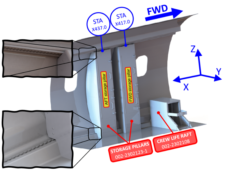
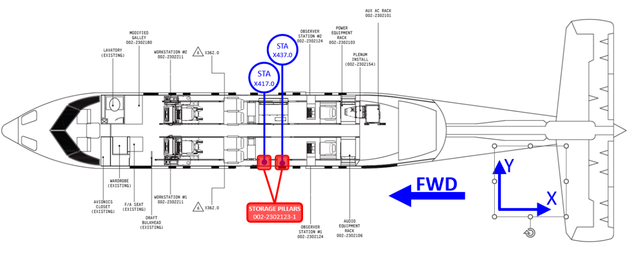
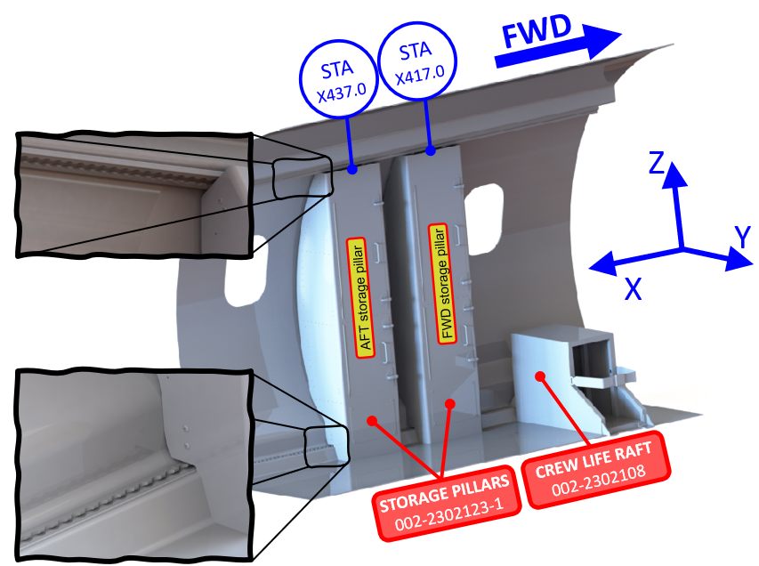
Both installations use the same structural design. The aft pillar was selected for detailed FEM substantiation because it sees the higher vertical ultimate demand; the forward pillar is covered by comparison. Loads from the shelves enter the pillar through their attachment hardware, distribute through the sheet/extrusion structure, and react at the upper and lower aircraft interfaces.
Analyze the unique governing configuration rather than duplicate two equivalent models. The aft pillar controls the detailed assessment because the geometry is common and its vertical ultimate load is higher.
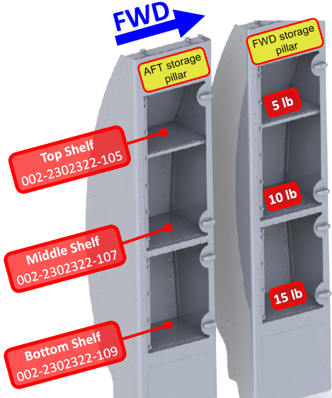
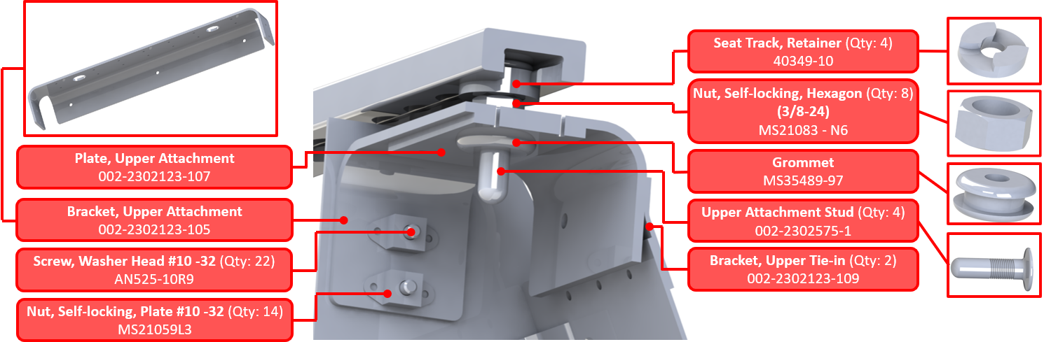
The primary structure uses 2024-T3 ALCLAD sheet and 6061-T6511 extrusions, with Gillfab 4030 shelf panels. Source allowables were taken from the applicable MMPDS material entries and hardware data. The FEM preserves both structural and non-structural inertia rather than explicitly modeling every accessory.
Ultimate tension 62 ksi; compression-yield allowable 37 ksi used for governing sheet checks.
Ultimate tension 38 ksi; compression-yield allowable 34 ksi used for governing extrusion checks.
Structure, removed/non-structural content, shelves and payload are retained at representative centers of gravity.
Key source joint allowables retained for the governing checks.
| Hardware | Source allowable used | Check type |
|---|---|---|
| MS20426AD4 rivet | 363 lbf | Shear |
| MS20470AD4 rivet | 389 lbf | Shear |
| AN525-10R joint | 1,496 lbf | Source-used governing joint value |
| Upper attachment stud | 341 lbf | Shear |
| Lower attachment stud | 2,000 lbf | Shear |
| NAS1834-3-500 insert | 1,166 / 645 lbf | Shear / tension |
The structural envelope combines governing flight loads with FAR 25.561 emergency-landing accelerations. Flight cases are converted to ultimate values as required by the source analysis; emergency values are already ultimate.
Governing ultimate load cases applied to the FEM.
| Load Case Number |
Load Factor Direction |
Ultimate Load Value ()[g] |
Governing basis |
|---|---|---|---|
| 1 | Up | 6.24 | Flight |
| 2 | Down | 7.995 | Flight |
| 3 | Outboard | 3.0 | Emergency landing |
| 4 | Inboard | 3.0 | Emergency landing |
| 5 | Forward | 9.0 | Emergency landing |
| - | Aft | 1.5 | Covered conservatively by Forward case |
Sheet and extrusion-wall behavior is captured with membrane, bending and shear response without unnecessary solid-element cost.
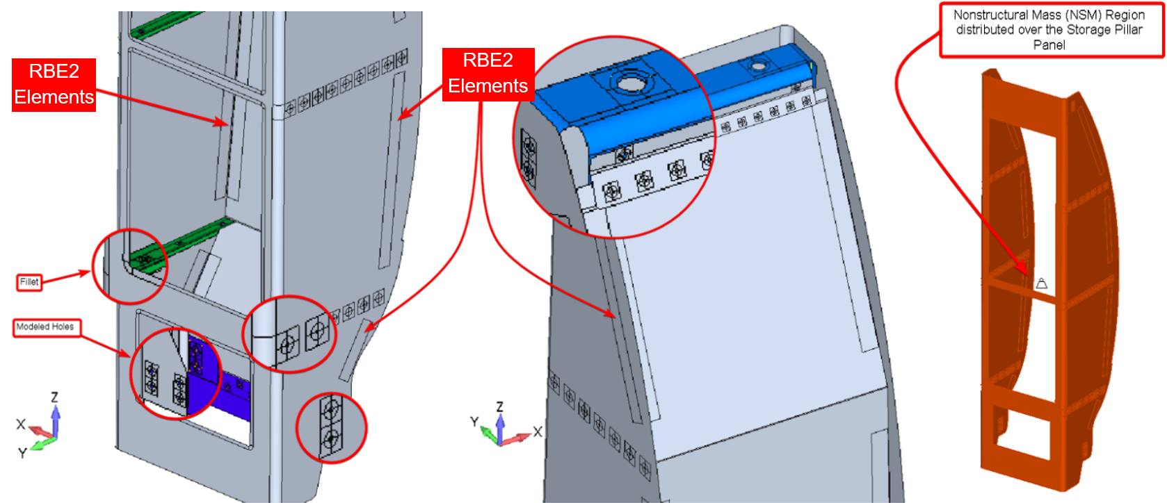
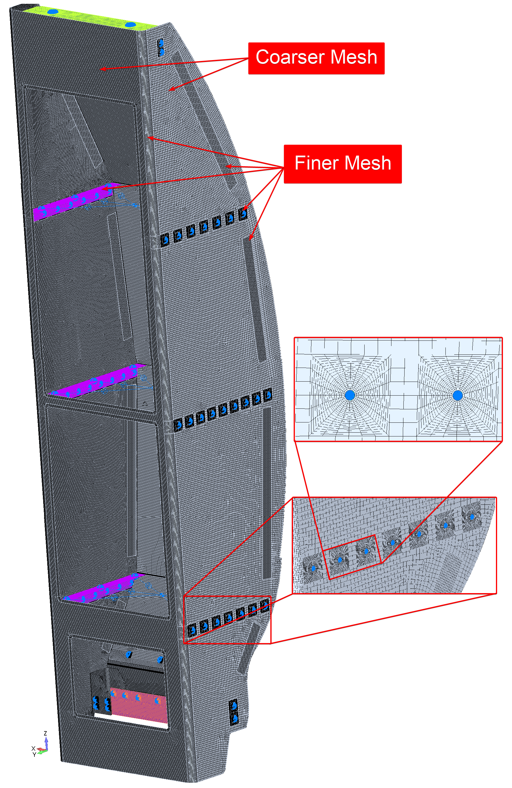
Fillets and structural fastener holes remain where local gradients matter; non-critical holes and accessory geometry are suppressed.
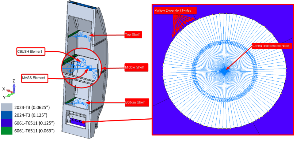
Fastener-hole spiders use 1×10⁷ lbf/in stiffness to transfer joint loads and permit direct connector-reaction recovery.
Mass elements place shelf inertia and overturning effects at the correct centers of gravity and transfer them into the attachment patterns.
The CAD geometry was simplified in FEMAP and midsurfaces extracted for the primary sheet structure. Non-structural accessories were removed from the mesh but their combined mass was retained. The Storage Pillar Panel-to-Back Panel interface was simplified with translational RBE2 coupling where the omitted rivet pattern was not required for the global load-path assessment.
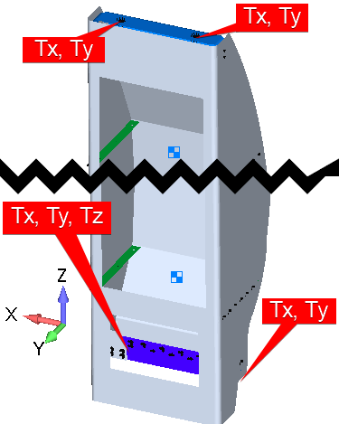
Tx and Ty restrained.
Forward lower attachmentTx and Ty restrained.
Aft lower attachmentTx, Ty and Tz restrained.
The restraint set follows the directional capability of the attachment system while avoiding unnecessary fixity. This preserves the intended reaction path and reduces artificial stiffening.
97.32% QUAD4 and only 0.46% TRI3. Local refinement is concentrated at holes, fillets and attachment regions; pads/washers stabilize hole-region load introduction.
Linear static analysis in SIMCENTER NASTRAN. WTMASS is enabled for the lbm–in–s unit system so force and stress output is interpreted consistently as lbf and psi.
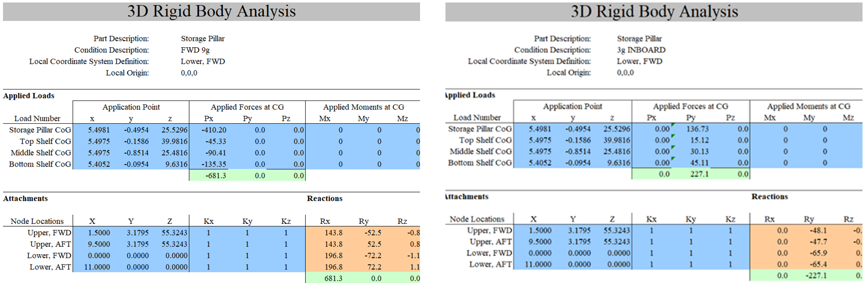
Before using the detailed stress and connector results, attachment reactions were cross-checked against an independent 3D rigid-body equilibrium model for the 9 g forward and 3 g inboard cases. The close agreement provides a global load-path sanity check independent of the FEM.
Reaction force comparison from the FE model and from the 3D Rigid Body Analysis.
| Node | Location | FWD | INBOARD | ||
|---|---|---|---|---|---|
| Rx | Ry | ||||
| FE | 3D-RBA | FE | 3D-RBA | ||
| 3548 | LOWER - AFT | 205.84 | 196.85 | -63.88 | -65.37 |
| 3761 | LOWER - FWD | 178.95 | 196.85 | -64.38 | -65.92 |
| 7880 | UPPER - AFT | 144.57 | 143.8 | -47.63 | -47.71 |
| 8007 | UPPER - FWD | 142.69 | 143.8 | -48.13 | -48.11 |
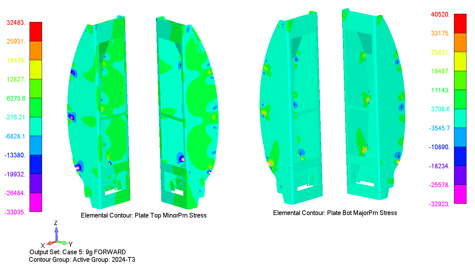
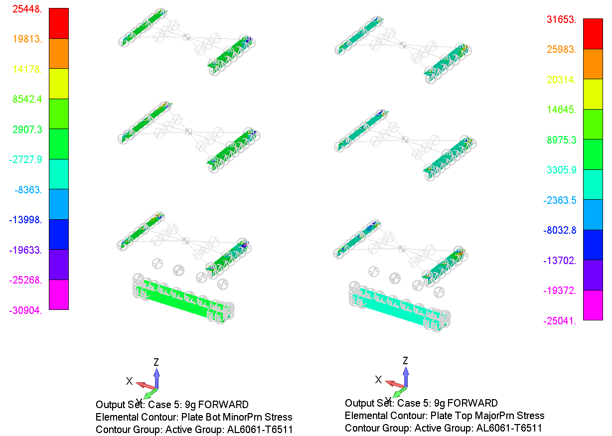
Principal stresses were reviewed on both plate faces for every load case. The raw FEM contains highly localized peaks beside retained holes and rigid-body connections; the source assessment identifies these as connection/geometric singularity-type effects and evaluates the surrounding structural stress field for the strength check. The localized peaks remain documented rather than being hidden.
Governing stress-field values used for material margins after the source peak-stress treatment.
| Material | Governing tensile stress | Tension allowable | Governing compression stress | Compression allowable | Minimum MS |
|---|---|---|---|---|---|
| 2024-T3 ALCLAD | 40.520 ksi | 62 ksi | 33.035 ksi | 37 ksi | +0.12 |
| 6061-T6511 | 31.653 ksi | 38 ksi | 30.904 ksi | 34 ksi | +0.10 |
Connector reactions were resolved into the applicable shear/tension components and compared with the source joint/fastener allowables using the report’s 1.15 fitting-factor convention where applied. Rather than repeating every connector table, the governing demand for each hardware family is retained below.
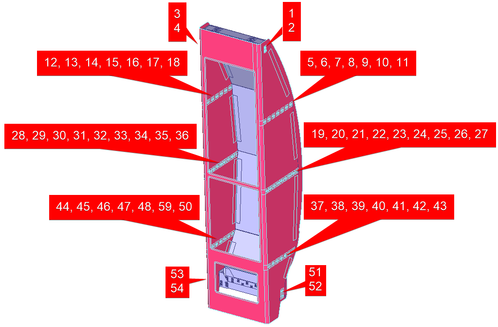
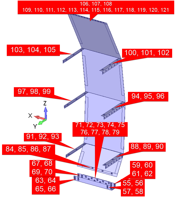
Governing connector / attachment results from the source analysis.
| Check | Governing demand | Source allowable / basis | Result |
|---|---|---|---|
| MS20426AD4 rivet | 297.41 lbf shear · 9 g forward | 363 lbf · 1.15 factor | MS = +0.06 |
| MS20470AD4 rivet | 201.71 lbf shear · 3 g outboard | 389 lbf · 1.15 factor | MS = +0.68 |
| AN525-10R joint | 269.30 lbf shear · 7.995 g down | 1,496 lbf source-used value · 1.15 factor | MS ≫ 1 |
| Upper attachment stud | 146.60 lbf shear | 341 lbf · 1.15 factor | MS = +1.02 |
| Lower attachment stud | 230.79 lbf shear | 2,000 lbf · 1.15 factor | MS ≫ 1 |
| Shelf AN525-10R16 / inserts | 182.17 lbf shear; 83.62 lbf tension · 9 g forward | 1,166 / 645 lbf minimum insert shear/tension values cited by source | PASS by observation |
Representative governing rivet calculation:
Attachment-stud checks: